
Quadrupole ion trap device and methods of operating a quadrupole ion trap device

a technology of quadrupole ion and trap device, which is applied in the field of quadratic mass spectrometry, can solve the problems of ion loss, quadrupole ion trap with significant high-order multipole components cannot work in mass-selective storage mode, and introduce many problems

Active Publication Date: 2007-10-23
SHIMADZU RES LAB EURO
View PDF13 Cites 26 Cited by
  • Summary
  • Abstract
  • Description
  • Claims
  • Application Information

AI Technical Summary

Benefits of technology

[0009]According to another aspect of the invention, there is provided a method of operating a quadrupole ion trap device including a ring electrode, and two end cap electrodes enclosing a trapping region one said end cap electrode being an entrance end cap electrode having a central aperture through which ions can enter the trapping region, and a field adjusting electrode located outside the trapping region adjacent to the aperture of said entrance end cap electrode, the method including, generating a trapping electric field within the trapping region, generating an excitation electric field within the trapping region for resonantly exciting ions trapped by the trapping electric field, applying DC voltage to said field adjusting electrode to influence ion motion near the entrance aperture, and selectively controlling the applied DC voltage to improve efficiency with which ions enter the trapping region through said entrance aperture and to enhance resolution of mass isolation carried out on the trapped ions.

Problems solved by technology

However, while the non-linear resonance which is caused by the high order multipole components brings about certain improvements in performance, such as good mass resolution at fast scan, it also introduces many problems.
A quadrupole ion trap with significant high order multipole components cannot work in the mass-selective storage mode as is usual in the case of a quadrupole mass filter, because the non-linear resonance line which runs through the apex region of the well known (a-q) stability diagram causes ion loss.
Furthermore, the non-linear ion trap cannot provide high resolution for precursor ion selection when the resonance ejection method is used.
In practice, however, there is no easy way to implement such a device because both RF switching and precise tuning of coupling parameters are difficult to achieve.
Also, no account is taken of the problem of field distortion near the end cap apertures.
Such distortion causes chemical shift and delayed ejection which leads to poor resolution of mass analysis.

Method used


Image

  • Quadrupole ion trap device and methods of operating a quadrupole ion trap device
  • Quadrupole ion trap device and methods of operating a quadrupole ion trap device
  • Quadrupole ion trap device and methods of operating a quadrupole ion trap device

Examples


Embodiment Construction

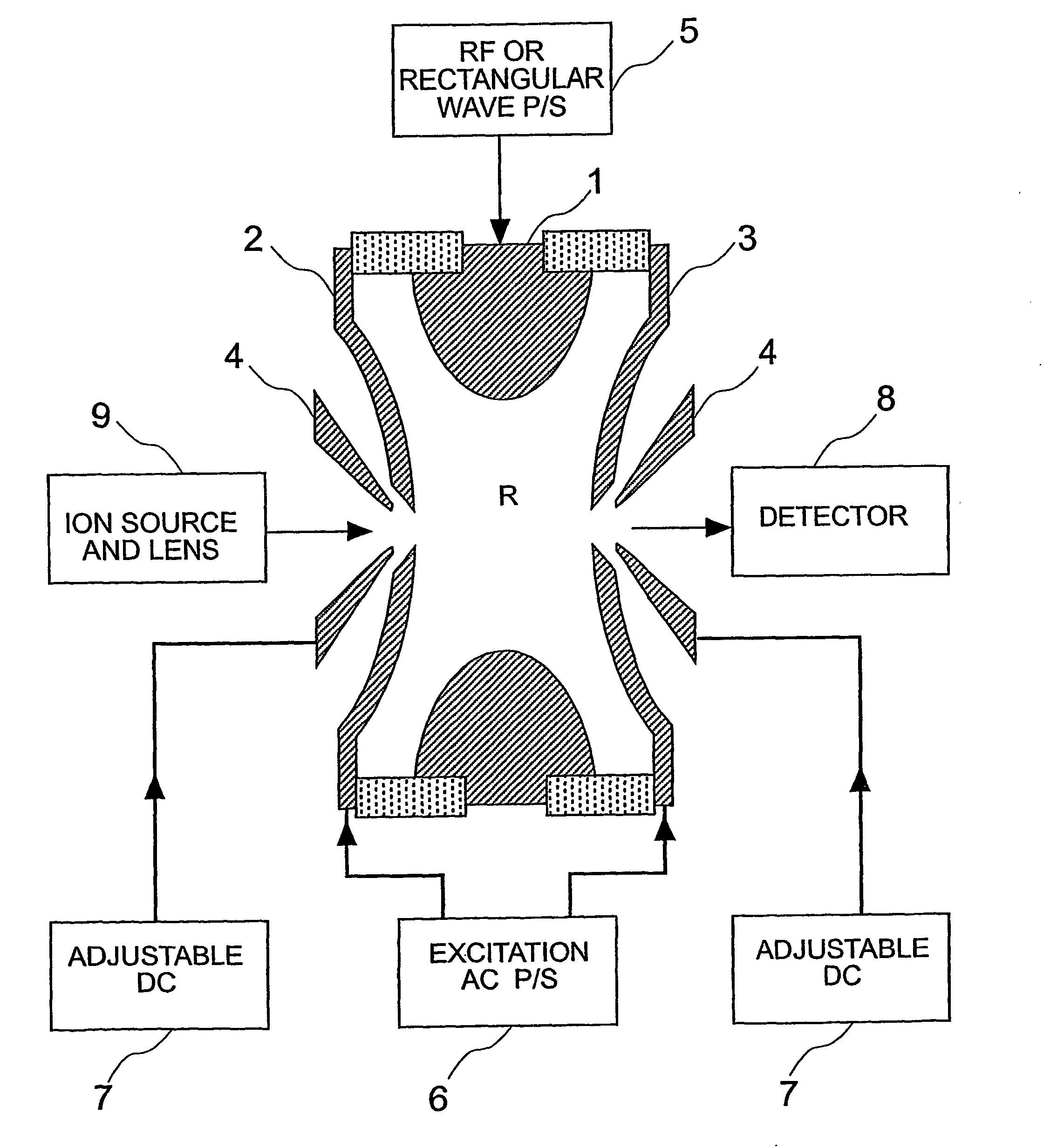
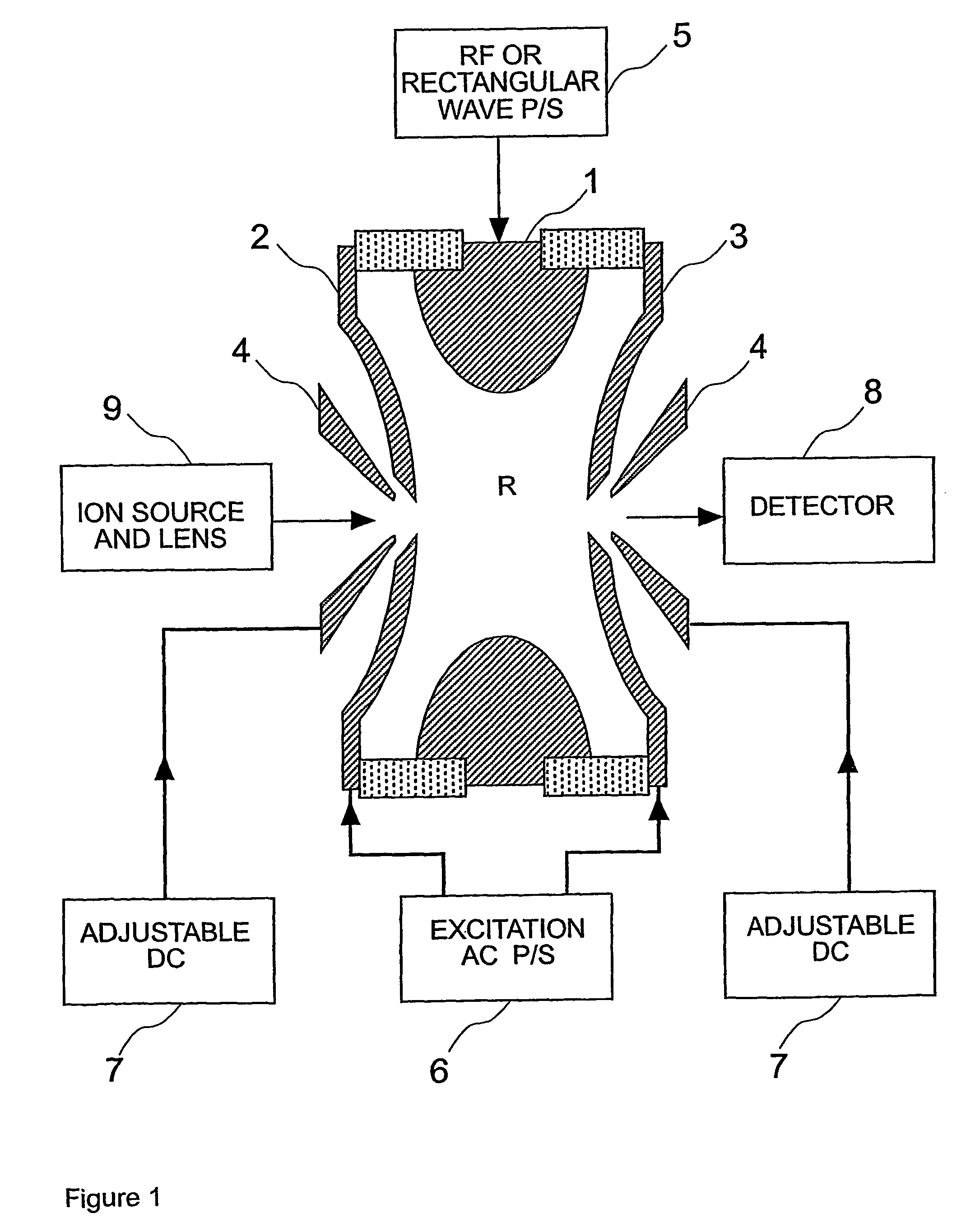
[0020]Referring now to FIG. 1, the quadrupole ion trap device comprises a ring electrode 1, an entrance end cap electrode 2 having a central entrance aperture, and an exit end cap electrode 3 having a central exit aperture, and these components enclose the trapping region R of the ion trap device.

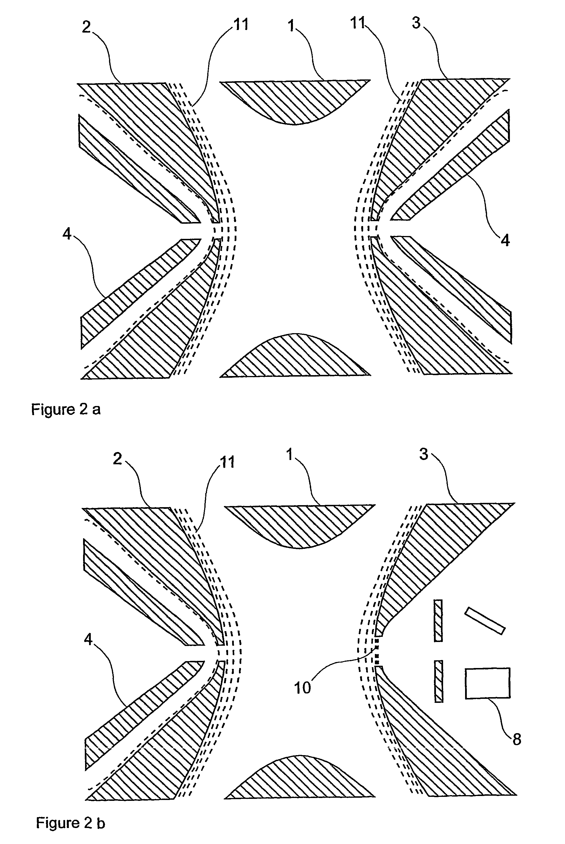
[0021]The device also includes a pair of field adjusting electrodes 4, located outside the trapping region. One of the field adjusting electrodes 4 is located adjacent to the entrance aperture of the entrance end cap electrode 2 and another field adjusting electrode 4 is located adjacent to the exit aperture of the exit end cap electrode 3, although this field adjusting electrode could optionally be omitted, as will be described later.

[0022]Ions produced in an ion source 9 are guided and focussed by conventional ion optics and are introduced into the trapping region R through an aperture in the field adjusting electrode 4 and then through the entrance aperture in the entrance end cap electr...


PUM


Abstract

A quadrupole ion trap device has a field adjusting electrode located outside the trapping region adjacent the aperture in the entrance end cap electrode, and optionally adjacent the aperture in the exit end cap electrode. The field adjusting electrode(s) controls field distortion in the vicinity of the apertures. By appropriately setting the voltages on the field adjusting electrodes the efficiency and resolution of operational processes such as ion introduction, precursor ion isolation and mass scanning can be improved.

Description

RELATED APPLICATIONS[0001]This application is the National Stage of International Application No. PCT / GB02 / 04807, filed Oct. 24, 2002, entitled A QUADRUPOLE ION TRAP DEVICE AND METHODS OF OPERATING A QUADRUPOLE ION TRAP DEVICE, which claims priority benefit of United Kingdom (GB) Application No. 0126525.5, filed Nov. 5, 2001. This U.S. National Stage Application also claims priority benefit of United Kingdom (GB) Application No. 0126525.5, filed Nov. 5, 2001.FIELD OF THE INVENTION[0002]This invention relates to quadrupole mass spectrometry. In particular, the invention relates to a quadrupole ion trap device and methods of operating a quadrupole ion trap device.BACKGROUND OF THE INVENTION[0003]The quadrupole ion trap has been developed and, used in practice, as a mass spectrometer since the mass selective instability mode was invented several decades ago. This technique is described in U.S. Pat. No. 4,540,884. Later, in a series of the US patents such as those numbered U.S. Pat. Nos...

Claims


Application Information

Patent Timeline
IPC IPC(8): H01J49/42G01N27/62H01J49/06
CPCH01J49/424H01J49/06
Inventor DING, LISUDAKOV, MICHAEL
Owner SHIMADZU RES LAB EURO
Learn More