
Pulsed-inertial electric motor

a technology of electric motors and electric motors, applied in mechanical energy handling, transportation and packaging, windings, etc., can solve the problems of complex control system and high-voltage power supply, motor-wheels offering no prospects for electric energy recovery, and high heat evolution, so as to improve the performance characteristics, simple design, and high reliability

Inactive Publication Date: 2007-10-23
ULTRA MOTOR CO LTD
View PDF20 Cites 18 Cited by
  • Summary
  • Abstract
  • Description
  • Claims
  • Application Information

AI Technical Summary

Benefits of technology

[0016]The aim of the present invention is to provide an electric motor with increased performance characteristics, relatively simple design, and high reliability.
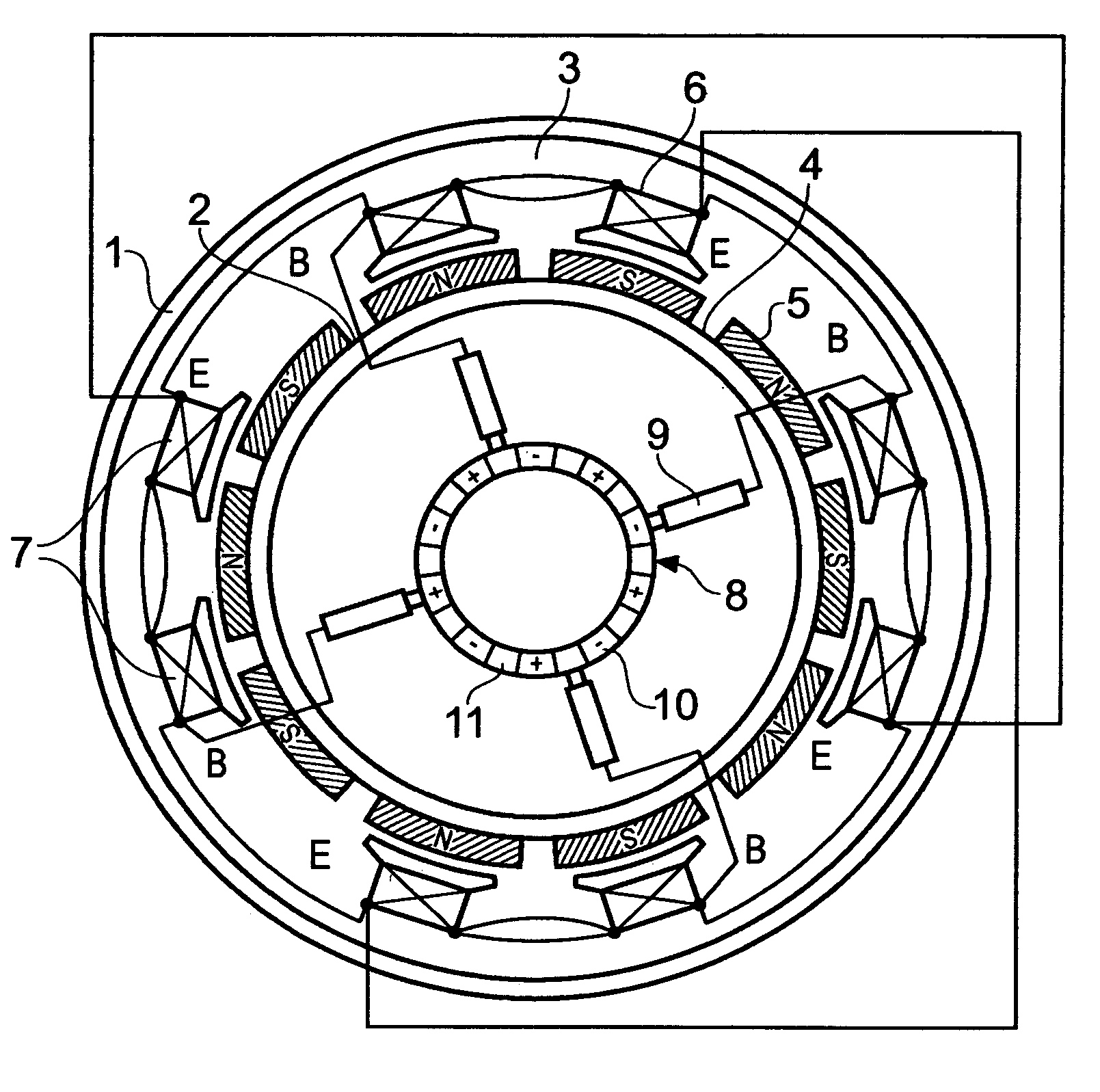
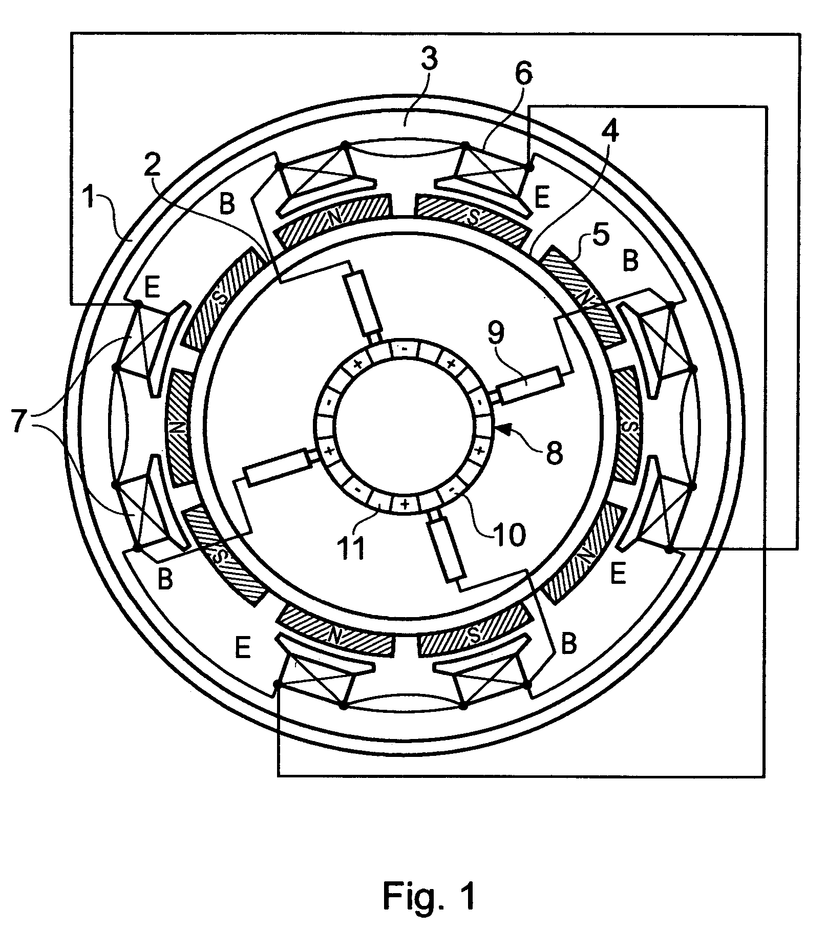
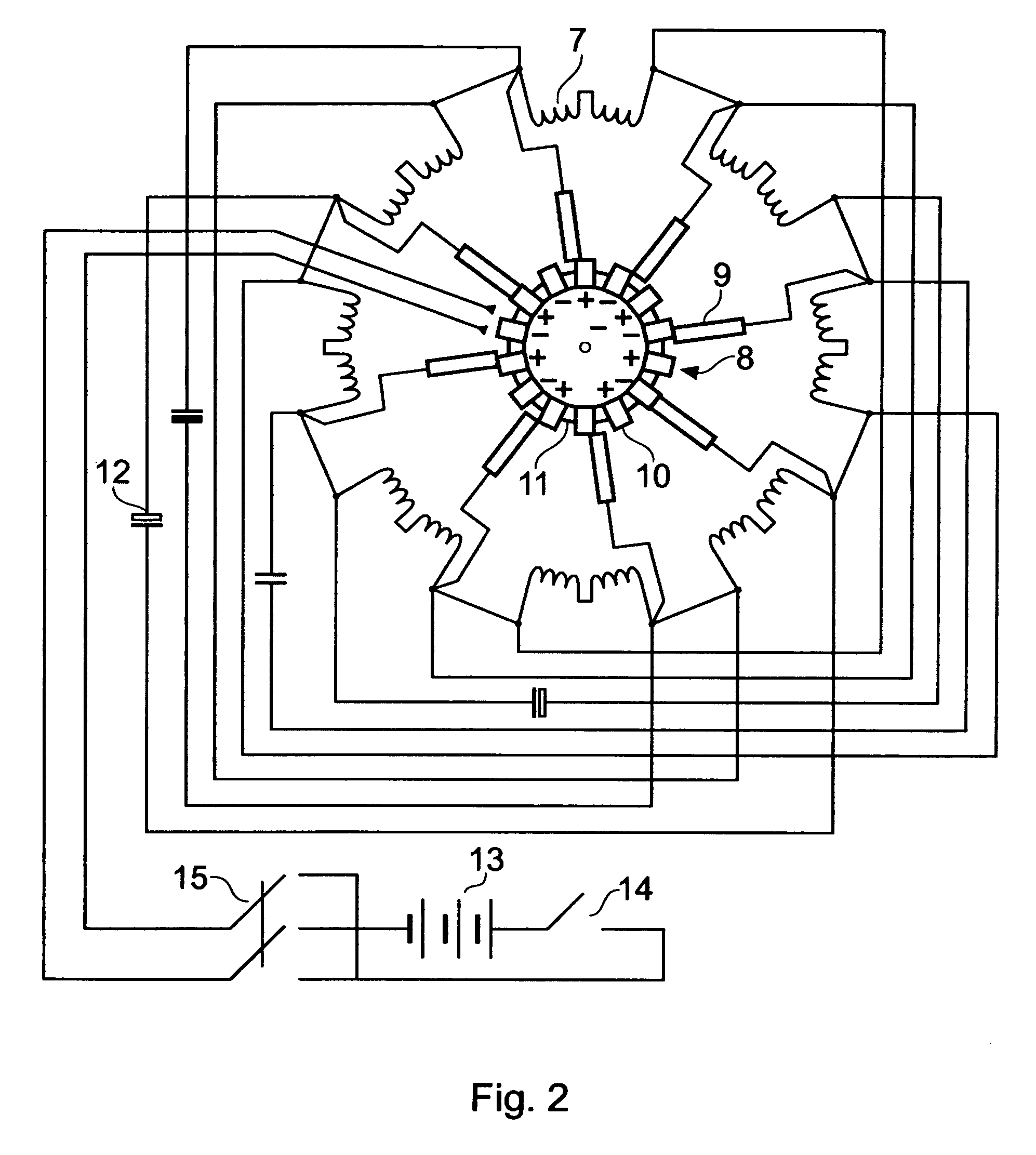
[0019]The number (n) of permanent magnets in the stator and the number (m) of electromagnets in the rotor are selected so as to obey the relationsn=10+4k,where k is an arbitrary integer (k=0, 1, 2, . . . ), andm=4+2l,where l is any integer such that 0≦l≦k. The numbers of permanent magnets and electromagnets are most frequently selected as follows: n=10, m=4; n=14, m=6; n=18, m=4; n=22, m=4, 6, 8, 10; n=26, m=4, 6, 8, 10, 12, and so on. For the proposed arrangement of magnets and the adopted scheme of commutation, these relations provide for a resonance of currents in the coils of opposite electromagnets, which decreases the voltage jumps in the start-up and acceleration regimes and improves dynamic characteristics of the motor. In addition, this scheme ensures a maximum recuperation of electric energy due to the counter-emf development in the free-run regime.
[0020]In one preferred embodiment, the coils of the opposite electromagnets connected to the brushes are shunted by capacitors so as to form resonance circuits. This additionally improves dynamic characteristics of the motor and practically eliminates sparking at the collector brushes. The capacitance of such shunting capacitors is increased in proportion to the number of turns in the coils of electromagnets. It is also desired that all resonance circuits formed by these capacitors and coils would have the same resonance frequency.

Problems solved by technology

However, use of the asynchronous electric motor still leads to high heat evolution and requires a complicated control system and high-voltage power supply.
Such a motor-wheel offers no prospects in electric energy recuperation during motion of retardation of the vehicle.
Advantages of such design are the absence of a reducing gear, use of low-voltage power sources, absence of supplementary electronic circuits, possibility of energy recuperation, and small size and weight.
However, the above motor-wheel and its analogs still have some disadvantages, the main of these being large start and transient currents in course of starting and accelerating the vehicle.
This leads to rapid degradation and a decrease in the working life of storage batteries and to unfavorable thermal regimes.
Another drawback is low efficiency of recovery and use of electric energy.
Finally, said electric motors are characterized by relatively low torque, which considerable reduces the field of possible practical applications.
Technical solutions suggested to eliminate these disadvantages are based on the use of high-voltage power sources and complicated control schemes, which increase the cost and decrease reliability of such systems in exploitation.

Method used


Image

  • Pulsed-inertial electric motor
  • Pulsed-inertial electric motor
  • Pulsed-inertial electric motor

Examples


example 1

[0040]A prototype electric motor was constructed with a stator involving 22 permanent magnets, a rotor involving three pairs of electromagnets, and the coils in each electromagnet containing 68 turns of an 1.06-diam wire. The motor has the following parameters: diameter, 300 mm; width 50 mm; weight, 7.5 kg; power consumption, 240 W; supply voltage, 24 V; torque, 9.6 N / m.

[0041]This motor was used as a motor-wheel in a bicycle of the STELS type with 26″ wheels. The current source comprised a pair of 12-V storage batteries, each with a capacity of 20 A / h. The bicycle with an electric drive based on the proposed motor was tested to show the following characteristics: weight-carrying capacity, 120 kg; cruising speed, 25 km / h; maximum run (for a storage battery discharged to 10.5 V), 40 km.

example 2

[0042]A prototype electric motor was constructed with a stator involving 22 permanent magnets, a rotor involving five pairs of electromagnets, and the coils in each electromagnet containing 50 turns of an 1.25-diam wire. The motor has the following parameters: diameter, 300 mm; width 60 mm; weight, 9.6 kg; power consumption, 1000 W; supply voltage, 48 V; torque, 40 N / m.

[0043]This motor was used as a motor-wheel in a scooter type with 16″ motorcycle wheels. The current source comprised four 12-V storage batteries, each with a capacity of 20 A / h. The scoter with an electric drive based on the proposed motor was tested to show the following characteristics: weight-carrying capacity, 150 kg; cruising speed, 45 km / h; maximum speed, 60 km / h; maximum run (for a storage battery discharged to 10.5 V), 50 km.

example 3

[0044]A prototype electric motor was constructed with a stator involving 18 permanent magnets, a rotor involving four pairs of electromagnets, and the coils in each electromagnet containing 55 turns of an 1.32-diam wire. The motor has the following parameters: diameter, 306 mm; width 72 mm; weight, 11 kg; power consumption, 1500 W; supply voltage, 48 V; torque, 52 N / m.

[0045]Two such motors were used as motor-wheels in a three-wheel carriage with 16″ motorcycle wheels for a driver and two passengers. The current source comprised four 12-V storage batteries, each with a capacity of 60 A / h. The carriage with an electric drive based on the proposed motor was tested to show the following characteristics: weight-carrying capacity, 500 kg; cruising speed, 45 km / h; maximum speed, 70 km / h; maximum run (for a storage battery discharged to 10.5 V), 70 km.

[0046]All measurements disclosed herein are at standard temperature and pressure, at sea level on Earth, unless indicated otherwise.


PUM


Abstract

The invention relates to electric motors, particularly to low-voltage gearless commutator motors, and can be used as motor-wheels in transportation vehicles and in other technologies. The aim of the present invention is to provide an electric motor with increased performance characteristics, relatively simple design, and high reliability. A pulsed inertial electric motor according to the invention comprises: (i) a stator with circular magnetic conductor on which an even number of permanent magnets are uniformly arranged with a certain pitch; (ii) a rotor separated from the stator by air gap and bearing an even number of electromagnets, each electromagnet consisting of two coils with opposite winding directions connected in series, which are arranged over the circle in pairs one opposite to another; (iii) a collector distributor mounted on the stator body, containing circularly arranged current-conducting plates separated by insulating spacers and connected with alternating polarity to a dc current source, and (iv) current collectors-brushes mounted on the rotor and capable of contacting with plates of the collector distributor, whereby all brushes are connected to identical (beginning or end) terminals of the windings of said electromagnets and interconnected so that the coils in the opposite electromagnets are connected to each other via one identical terminal and to the opposite brushes via another identical terminal, with the number n of permanent magnets in the stator and the number m of electromagnets in the rotor selected so as to obey the relationsn=10+4k,m=4+2l,where k is an arbitrary integer (k=0, 1, 2, . . . ) and l is any integer such that 0≦l≦k.

Description

CROSS-REFERENCE TO RELATED APPLICATIONS[0001]This is a continuation-in-part of my U.S. patent application Ser. No. 10 / 824,205, filed 14 Apr. 2004, now U.S. Pat. No. 6,975,054 and incorporated herein by reference, which is a continuation of International Application No. PCT / RU2003 / 00178, filed 18 Apr. 2003, priority of which is hereby claimed, and which is incorporated herein by reference.[0002]Priority of my Russian Patent Application No. 2005110334 filed 11 Apr. 2005, and incorporated herein by reference, is hereby claimed.[0003]U.S. Patent Publication No. US 2004 / 0239204 A1 is incorporated herein by reference.[0004]Priority of my U.S. Provisional Patent Application No. 60 / 512,652, filed 20 Oct. 2003, and incorporated herein by reference, is hereby claimed.[0005]Incorporated herein by reference is my International Application No. PCT / RU2003 / 00178, filed 18 Apr. 2003, and its publication, No. WO 2004 / 091957, published on 28 Oct. 2004.STATEMENT REGARDING FEDERALLY SPONSORED RESEARCH ...

Claims


Application Information

Patent Timeline
Patent Type & Authority Patents(United States)
IPC IPC(8): H02K13/04B60K7/00H02K21/26H02K23/04H02K25/00
CPCH02K25/00
Inventor SHKONDIN, VASILY VASILIEVICH
Owner ULTRA MOTOR CO LTD
Learn More