Image display unit

a technology of image display and display unit, which is applied in the direction of polarising elements, television systems, instruments, etc., can solve the problems of high production cost, and inability to manufacture the entire image display devi

Active Publication Date: 2007-10-23
SONY CORP
View PDF11 Cites 80 Cited by
  • Summary
  • Abstract
  • Description
  • Claims
  • Application Information

AI Technical Summary

Benefits of technology

[0027]It is an object of the present invention to provide a new image display device that can solve problems of a usual image display device.
[0028]It is another object of the present invention to provide an image display device for forming a virtual image of an image display element and displaying an image, in which the thickness of an optical system is decreased, its weight is reduced and an entire device can be made compact and its weight can be reduced.
[0029]It is a still another object of the present invention to provide an image display device in which an exit pupil diameter, a display angle of view and an eye relief can be increased while an entire device can be made compact and its weight can be reduced and an aberration is reduced.
[0034]In the present invention, an optical medium having a refractive index larger than 1 is disposed in an optical path between the image display element and the transmission type diffraction optical element. Thus, the length of the optical path between the image display element and the transmission type diffraction optical element in terms of air can be decreased and an effective focal length to the reflection type optical element having the positive optical power can be decreased. Consequently, the enlargement magnification of an optical system can be increased and the size of the optical system can be cut down.
[0035]The image display device according to the present invention has an arrangement structure that the image display element and the reflection type optical element having the positive optical power are optically eccentrically arranged. Thus, an entire optical system can be realized, which is thinner and lighter than an optical system of other system having the same exit pupil diameter and display angle of view. The image display device according to the present invention has a decentered optical system so that the transmission type diffraction optical element can correct the generated eccentric aberration and the optical system high in its resolving power can be realized.

Problems solved by technology

The polarized beam splitter cube 125 forming the image display device shown in FIG. 1 is hardly produced and a production cost thereof is high.
Accordingly, the manufacture of the entire image display device is difficult and the manufacture cost thereof is undesirably increased.
The polarized beam splitter cube forming the image display device is hardly produced and a production cost thereof is high.
Accordingly, the manufacture of the entire image display device is difficult and the manufacture cost thereof is undesirably increased.
In the optical system having such a quantity of eccentricity, an enormous quantity of eccentric aberration is generated.

Method used


Image

  • Image display unit
  • Image display unit
  • Image display unit

Examples


Embodiment Construction

[0045]Now, an image display device according to the present invention will be described below by referring to the drawings.

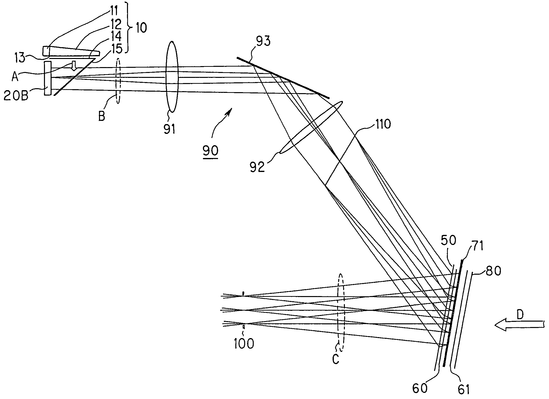
[0046]The image display device according to the present invention includes, as shown in FIG. 4, an illuminating light source device 10, a transmission type spatial light modulator 20A, an HPDLC optical element 50 as a transmission type diffraction optical element, two quarter-wave plates 60 and 61, an adjustable curved face semi-transmission mirror 70 as a reflection type optical element having a positive optical power and a polarizing plate 80.

[0047]The light source device 10 uses a semiconductor laser 11 as a light source. The light source device 10 includes a light guide plate 12 for guiding a light flux emitted from the semiconductor laser 11 and an optical film 14. Lights emitted from the semiconductor laser 11 are incident on the light guide plate 12 made of a synthetic resin. The lights with illumination intensity uniformed and angle of emergence controll...


PUM


Abstract

The present invention relates to an image display device in which a virtual image of an image display element is formed to display an image. The image display device includes a transmission type diffraction optical element (50) for diffracting exit lights from the image display element (20) and a reflection type optical element (70) having a positive optical power for reflecting the diffracted lights from the transmission type diffraction optical element (50). When the reflected lights reflected by the reflection type optical element (70) are incident again on the transmission type diffraction optical element (50), the transmission type diffraction optical element (50) diffracts the reflected lights with a diffraction efficiency lower than a diffraction efficiency for the exit lights from the image display element (20).

Description

BACKGROUND OF THE INVENTION[0001]The present invention relates to an image display device preferably used for a view finder of a video camera or a head mounted type display or the like, and more particularly to a glasses type virtual image display device having a see-through function.[0002]This application of the invention claims a priority based on Japanese Patent Application No. 2002-124824 filed in Apr. 25, 2002 in Japan. The earlier application is applied to this application by referring thereto.[0003]An image display device used as a view finder of a video camera or a head mounted type display or the like has been hitherto proposed. As such an image display device, a virtual image display device formed by using a reflection type spatial light modulator is proposed.[0004]As one example of this kind of image display device, an image display device is disclosed in the description of U.S. Pat. No. 5,596,451. The image display device described in this description has a polarized bea...

Claims


Application Information

Patent Timeline
Patent Type & Authority Patents(United States)
IPC IPC(8): G03H1/00G02B5/18G02B5/30G02B5/32G02B17/00G02B27/00G02B27/01G02B27/02H04N5/225H04N5/64
CPCG02B5/1876G02B5/3016G02B27/0172G02B5/32G02B5/30G02B2027/0123G02B6/00G02B2027/012G02B27/02
Inventor MUKAWA, HIROSHI
Owner SONY CORP
Why Eureka
Try Eureka