Perpendicular magnetic recording medium, method for manufacturing the same, and magnetic recording/reproducing apparatus

a technology of magnetic recording medium and manufacturing method, which is applied in the field of perpendicular magnetic recording medium, method for manufacturing the same, and magnetic recording/reproducing apparatus, etc., can solve the problems of increasing the noise generated by the medium, increasing the recording density, and reducing the recording quality

Inactive Publication Date: 2007-10-30
KK TOSHIBA +1
View PDF10 Cites 5 Cited by
  • Summary
  • Abstract
  • Description
  • Claims
  • Application Information

AI Technical Summary

Benefits of technology

[0011]First, the present invention provides a perpendicular magnetic recording medium comprising a substrate, an underlayer formed on the substrate, and a perpendicular magnetic recording layer formed on the underlayer, having an easy axis of magnetization oriented perpendicularly to the subst

Problems solved by technology

In a longitudinal magnetic recording medium, recording bits of a magnetic recording layer may become too small as the recording density increases.
If this is the case, a so-called thermal decay effect by which information in these recording bits is thermally erased may worsen the recording/reproduction characteristics.
Additionally, as the recording density increases, noise generated from the medium tends to increase due to the influence of an antimagnetic field generated in the boundary between the recording bits.
However, downsizing of magnetic grains by Cr segregation has its limits.
Therefore, sep

Method used


Image

  • Perpendicular magnetic recording medium, method for manufacturing the same, and magnetic recording/reproducing apparatus
  • Perpendicular magnetic recording medium, method for manufacturing the same, and magnetic recording/reproducing apparatus
  • Perpendicular magnetic recording medium, method for manufacturing the same, and magnetic recording/reproducing apparatus

Examples


embodiment 1

[0060]A 2.5-inch, hard-disk-like nonmagnetic glass substrate was prepared.

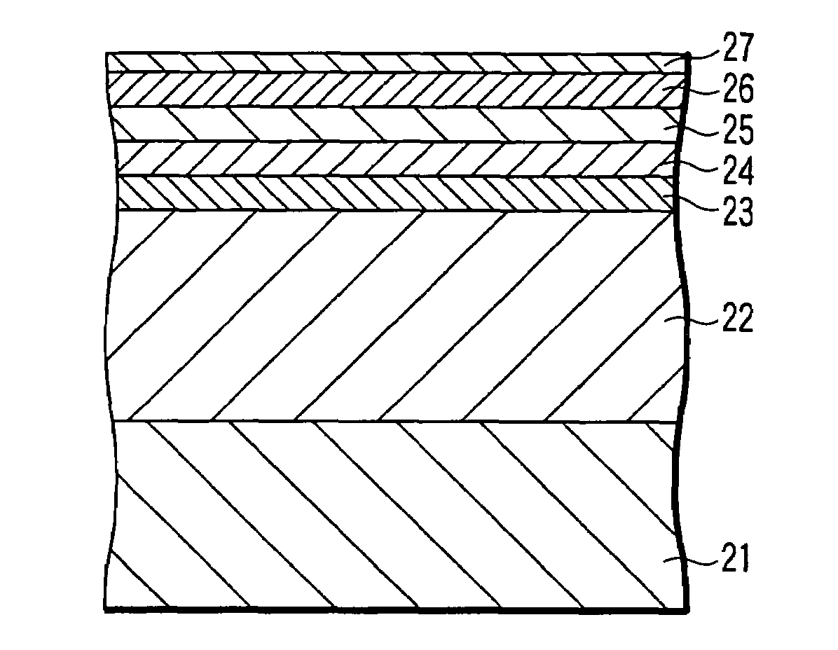
[0061]After a vacuum chamber of a sputtering apparatus was evacuated to 2×10⁻⁵ Pa or less, a 200-nm thick Co84Zr6Nb10 soft magnetic layer and 8-nm thick Ta layer were formed as a soft magnetic layer and first underlayer, respectively, in a 0.67-Pa Ar ambient by using a Co84Zr6Nb10 target and Ta target, respectively. After that, a 15-nm thick Ru layer was stacked as a second underlayer in a 3-Pa Ar ambient.

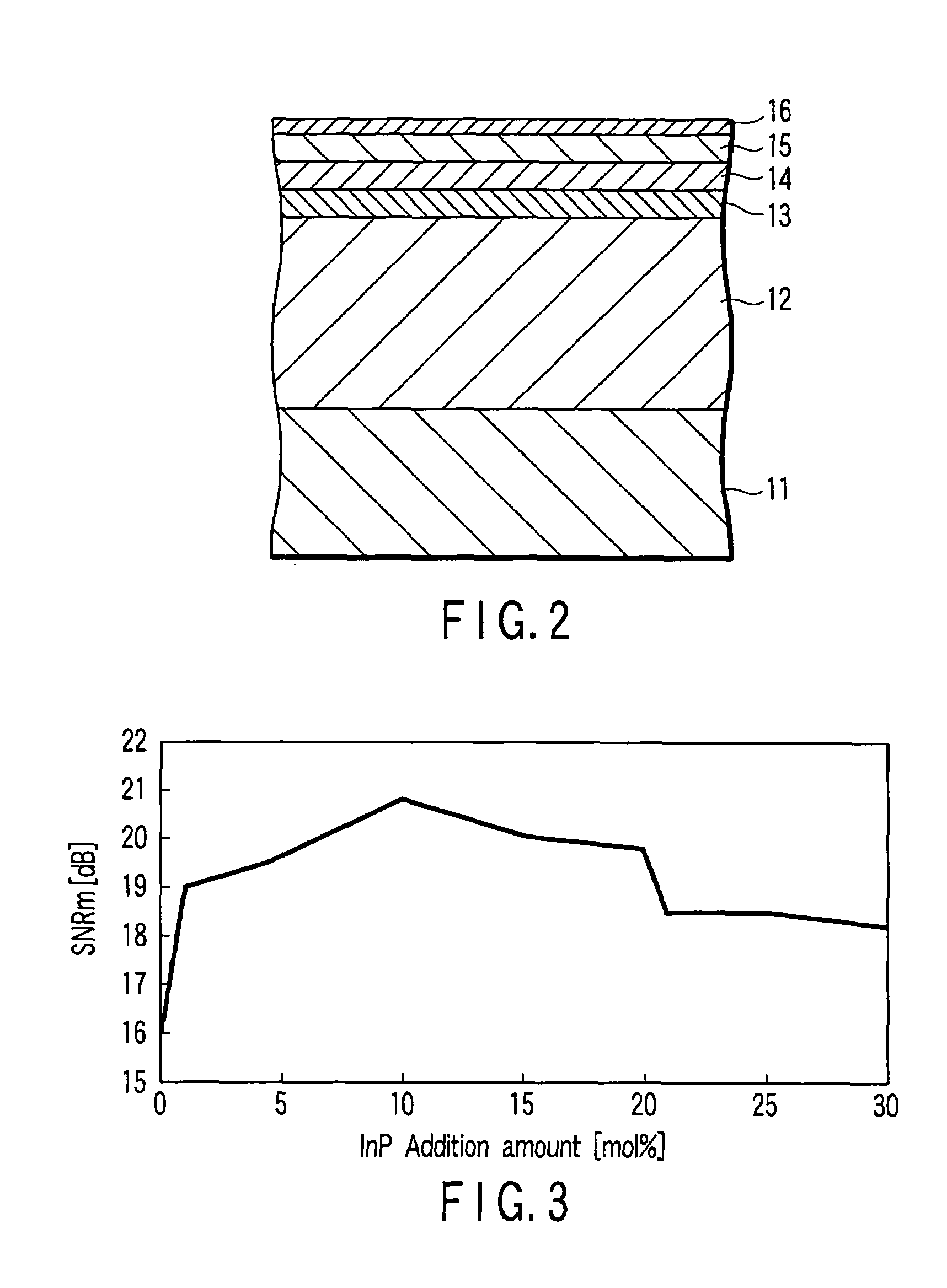
[0062]Subsequently, a 20-nm thick magnetic recording layer was formed by using a composite target obtained by adding 0 to 30 mol % of InP as a matrix material to Co-10 at % Cr-14 at % Pt as a magnetic crystal grain material. A 7-nm thick C layer was then stacked as a protective layer in a 0.67-Pa Ar ambient. After the film formation, the surface of the protective layer was coated with a 13-Å thick perfluoropolyether (PFPE) lubricating agent by dipping, thereby obtaining a magnetic recording medium. The electr...

embodiment 2

[0081]A 2.5-inch, hard-disk-like nonmagnetic glass substrate was prepared.

[0082]After a vacuum chamber of a sputtering apparatus was evacuated to 2×10⁻⁵ Pa or less, a 5-nm thick Ta layer was formed as a first underlayer in a 0.67-Pa Ar ambient. After that, a 15-nm thick Ru layer was stacked as a second underlayer in an 8-Pa Ar ambient.

[0083]Subsequently, a 15-nm thick magnetic recording layer was formed in an 8-Pa Ar ambient by two-target simultaneous sputtering by using a Co-10 at % Cr-14 at % Pt target as a magnetic crystal grain material and an InP target as a matrix material. During this sputtering, the electric power to be applied to each target was so controlled as to appropriately change the addition amount of the matrix material between 0 and 30 mol % with respect to the magnetic crystal grain material. A 7-nm thick C layer was then stacked as a protective layer in a 0.67-Pa Ar ambient. After the film formation, the surface of the protective layer was coated with a 13-Å thic...

embodiment 3

[0094]A 2.5-inch, hard-disk-like nonmagnetic glass substrate was prepared.

[0095]After a vacuum chamber of a sputtering apparatus was evacuated to 2×10⁻⁵ Pa or less, a 200-nm thick Co84Zr6Nb10 soft magnetic layer, 5-nm thick Ta layer, and 15-nm thick Ru layer were formed as a soft magnetic layer, first underlayer, and second underlayer, respectively, in a 0.67-Pa Ar ambient by using a Co84Zr6Nb10 target, Ta target, and Ru target, respectively.

[0096]Subsequently, a 10-nm thick magnetic recording layer was formed in an 8-Pa Ar ambient by two-target simultaneous sputtering by using a Co-10 at % Cr-14 at % Pt target as a magnetic crystal grain material and an InP target as a matrix material. During this sputtering, the electric power to be supplied to each target was so controlled as to appropriately change the addition amount of the matrix material between 0 and 30 mol % with respect to the magnetic crystal grain material. A 7-nm thick C layer was then stacked as a protective layer in a...


PUM


Abstract

Disclosed is a magnetic recording medium which includes a substrate, an underlayer, and a perpendicular magnetic recording layer, and in which this perpendicular magnetic recording layer contains magnetic crystal grains and a matrix surrounding the magnetic crystal grains, and the matrix contains an element selected from Zn, Cd, Al, Ga, and In, and a component selected from P, As, Sb, S, Se, and Te.

Description

CROSS-REFERENCE TO RELATED APPLICATIONS[0001]This application is based upon and claims the benefit of priority from prior Japanese Patent Application No. 2003-097317, filed Mar. 31, 2003, the entire contents of which are incorporated herein by reference.BACKGROUND OF THE INVENTION[0002]1. Field of the Invention[0003]The present invention relates to a magnetic recording medium for use in a hard disk drive using the magnetic recording technique, a method of manufacturing the magnetic recording medium, and a magnetic recording / reproducing apparatus.[0004]2. Description of the Related Art[0005]A magnetic storage device (HDD) mainly used in computers to record and reproduce information is recently gradually extending its applications because of its large capacity, inexpensiveness, high data access speed, data holding reliability, and the like. The HDD is now used in various fields such as household video decks, audio apparatuses, and car navigation systems. As the range of use of the HDD...

Claims


Application Information

Patent Timeline
IPC IPC(8): G11B5/66G11B5/65G11B5/64G11B5/85H01F10/14H01F10/16H01F41/20
CPCG11B5/65G11B5/656G11B5/653
Inventor MAEDA, TOMOYUKIHIKOSAKA, TAKASHINAKAMURA, FUTOSHIIWASAKI, TAKESHISAKAI, HIROSHISHIMIZU, KENJISAKAWAKI, AKIRA
Owner KK TOSHIBA
Why Eureka
Try Eureka