
Engine control for low emission vehicle starting

a low-emission vehicle and engine control technology, applied in the direction of electric control, machines/engines, mechanical equipment, etc., can solve the problems of limited combustion stability, and limited catalyst light-off time, so as to reduce catalyst light-off time and reduce emission

Inactive Publication Date: 2007-11-13
FORD GLOBAL TECH LLC
View PDF29 Cites 18 Cited by
  • Summary
  • Abstract
  • Description
  • Claims
  • Application Information

AI Technical Summary

Benefits of technology

[0009]By waiting until the exhaust temperature reaches a pre-selected value (for example, a manifold auto-ignition temperature), it is possible to minimize the chance of unburned fuel passing through the exhaust system. Further, it is possible to use as little fuel as possible to achieve the desired rapid catalyst heating. In other words, the present invention withholds adding excess fuel to the engine until the exhaust temperature has reached a value that will support auto ignition of the rich exhaust gases and excess air introduced via the air introduction device.
[0011]An advantage of the above aspect of the present invention is reduced emission due to decreased catalyst light-off times.

Problems solved by technology

The inventors of the present invention have recognized that a disadvantage with the above approach is that the amount of ignition timing retard is limited by combustion stability.
This, in turn, limits the maximum amount of heat that can be added to the catalytic converter and thereby limits the ability to increase catalyst light-off times.
The inventors herein have also recognized a problem with the above approach.
In particular, the inventors have discovered that increased exhaust emissions may result due to incomplete burning of the excess hydrocarbons and injected airflow in the exhaust system.

Method used


Image

  • Engine control for low emission vehicle starting
  • Engine control for low emission vehicle starting
  • Engine control for low emission vehicle starting

Examples


Embodiment Construction

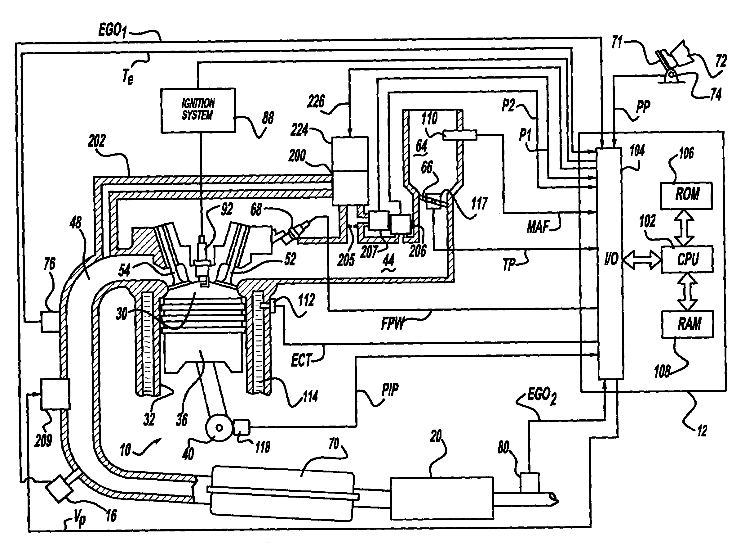
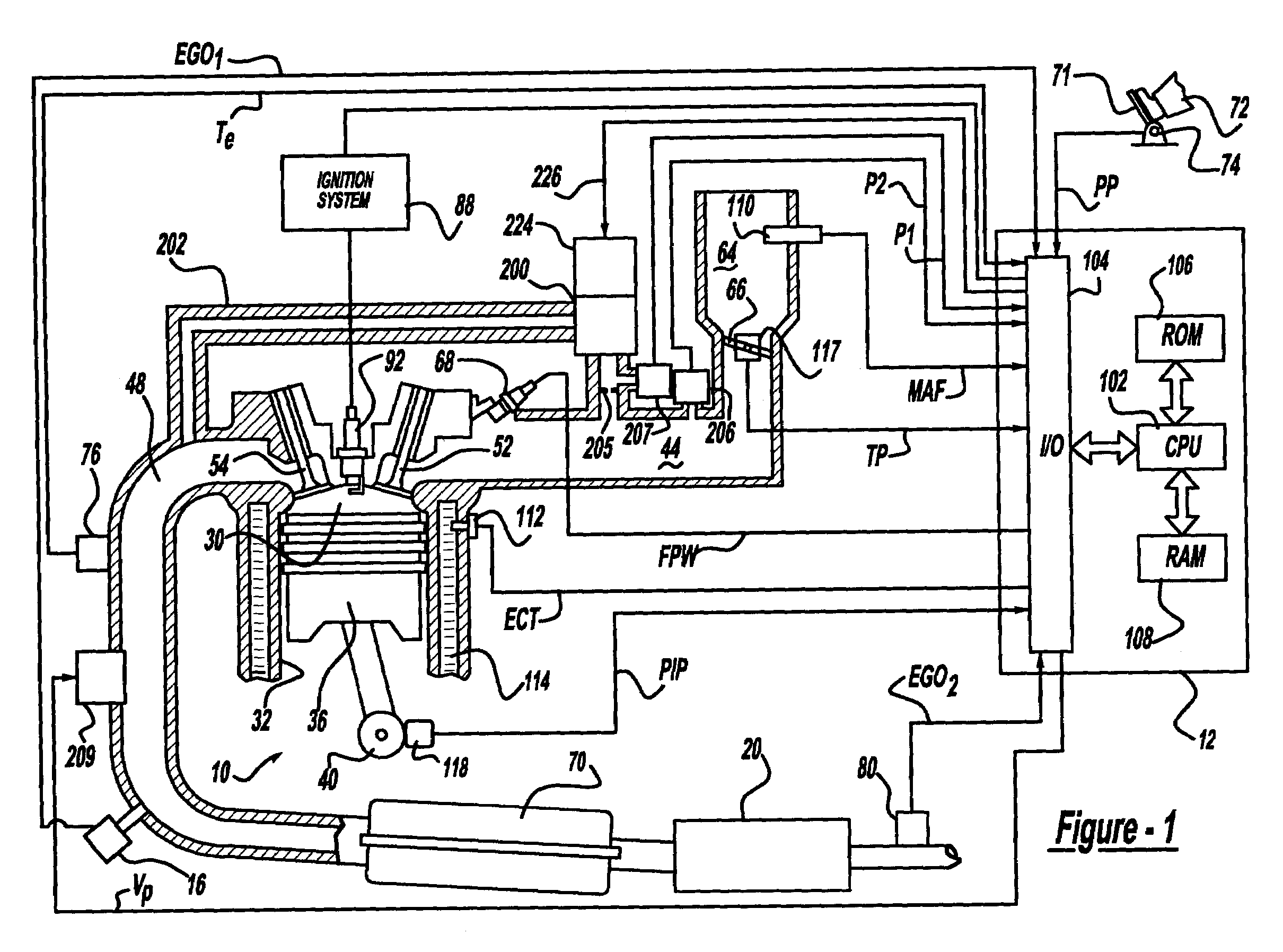
[0017]Internal combustion engine 10, comprising a plurality of cylinders, one cylinder of which is shown in FIG. 1, is controlled by electronic engine controller 12. Engine 10 includes combustion chamber 30 and cylinder walls 32 with piston 36 positioned therein and connected to crankshaft 40. Combustion chamber 30 communicates with intake manifold 44 and exhaust manifold 48 via respective intake valve 52 and exhaust valve 54. Exhaust gas oxygen sensor 16 is coupled to exhaust manifold 48 of engine 10 upstream of catalytic converter 20. In general terms, which are described later herein, controller 12 controls engine air / fuel ratio in response to feedback variable FV derived from two-state exhaust gas oxygen sensor 16.

[0018]As described above, two-state exhaust gas oxygen sensor 16 is shown coupled to exhaust manifold 48 upstream of catalytic converter 20. Two-state exhaust gas oxygen sensor 80 is also shown coupled to exhaust manifold 48 downstream of catalytic converter 20. Sensor...


PUM


Abstract

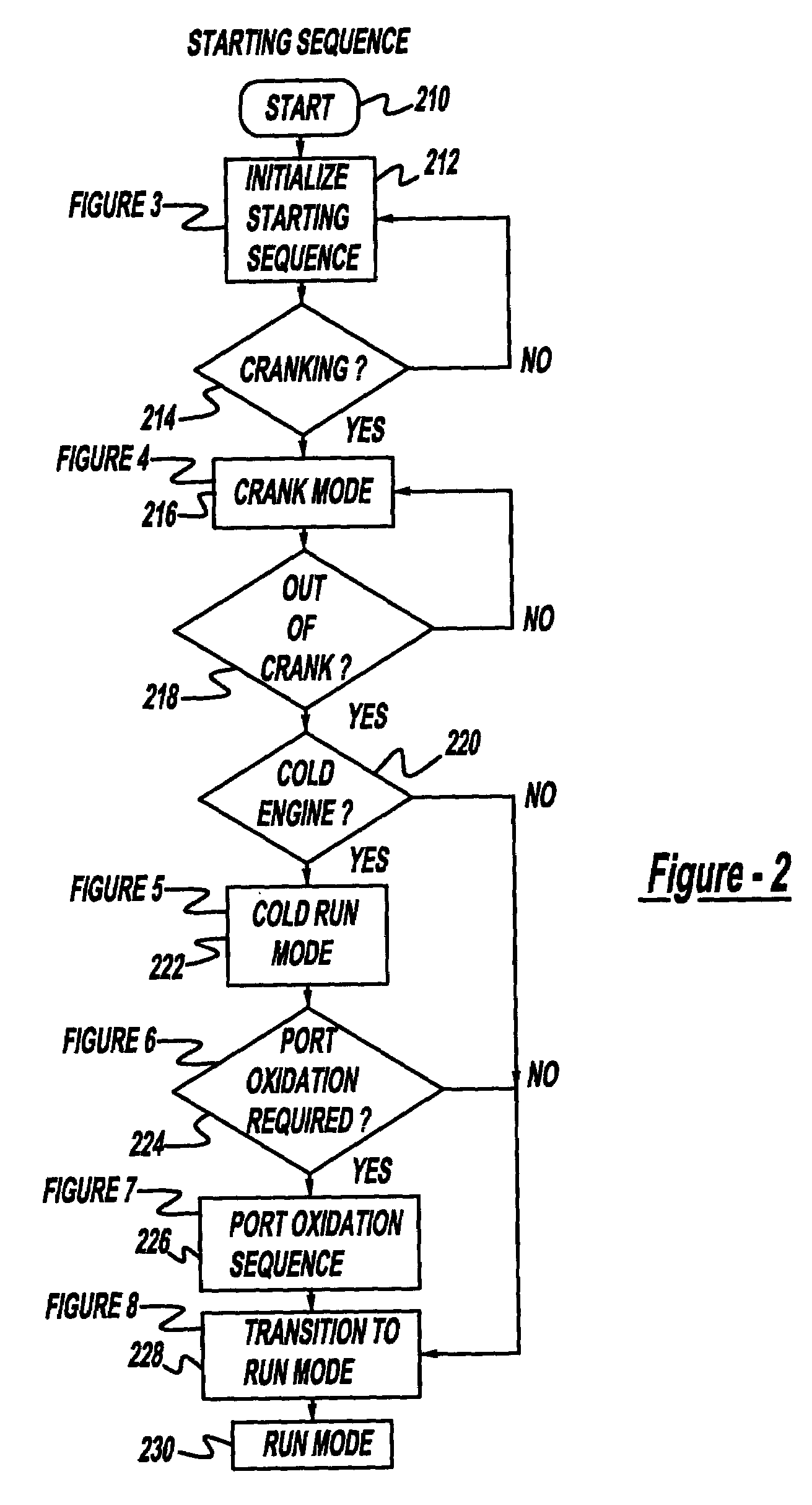
A method for rapidly heating an emission control device in an engine exhaust uses excess air added to the exhaust via an air introduction device. After an engine cold start, the engine is operated to raise exhaust manifold temperature to a first predetermined value by operating the engine with a lean air-fuel ratio and retarded ignition timing. Once the exhaust manifold reaches the predetermined temperature value, the engine is switched to operate rich and air is added via the air introduction device. The added air and rich exhaust gas burn in the exhaust, thereby generating heat and raising catalyst temperature even more rapidly. The rich operation and excess air are continued until either engine airflow increases beyond a pre-selected value, or the emission control device reaches a desired temperature value. After the emission control device reaches the desired temperature, the engine is operated substantially around stoichiometry. Further, a method is described for adaptively learning pump airflow using feedback from an exhaust gas oxygen sensor.

Description

CROSS-REFERENCE TO RELATED APPLICATIONS[0001]This application is a continuation application of Ser. No. 10 / 064,432 filed Jul. 12, 2002 now U.S. Pat. No. 6,640,539 and is hereby incorporated by reference. This application also claims the priority under 35 U.S.C. § 120, and is a continuation application, of the following U.S. patent applications, which are hereby incorporated by reference in their entirety for all purposes: U.S. patent application Ser. No. 10 / 064,430, filed Jul. 12, 2002 now U.S. Pat. No. 6,666,021; and U.S. patent application Ser. No. 10 / 064,433, filed Jul. 12, 2002 now U.S. Pat. No. 6,715,280.FIELD OF THE INVENTION[0002]The present invention relates generally to the control of an internal combustion engine having an air introduction device in the engine exhaust.BACKGROUND OF THE INVENTION[0003]To reduce engine emissions, it is desirable to rapidly heat catalytic converters in the engine exhaust. In other words, catalytic converters achieve higher emission reduction ...

Claims


Application Information

Patent Timeline
IPC IPC(8): F01N3/00F01N3/20F01N3/22F01N3/32F01N9/00F01N13/02F02D41/02F02D41/06F02M25/07
CPCF01N3/2006F01N13/009F01N3/225F01N3/323F01N9/005F02D41/0245F02D41/025F02D41/0255F02D41/064F02D41/1448F01N3/222F01N3/32F01N2430/06F01N2430/08F02D41/1441F02D41/1446F02D41/187F02D2200/0404F02D2200/0406F02D2200/0414F02D2200/602F02M25/0724F02M25/0754F02M25/0774Y02T10/26Y02T10/47F02M26/21F02M26/47F02M26/55Y02T10/12Y02T10/40Y02A50/20
Inventor LEWIS, DONALD JAMESKERNS, JAMES MICHAELGERHART, MATTHEW JOHNCUNNINGHAM, RALPH WAYNE
Owner FORD GLOBAL TECH LLC
Learn More