
Process for production of conductive catalyst particles, process for production of catalyst electrode capable of gas diffusion, apparatus for production of conductive catalyst particles, and vibrating apparatus

a technology of catalyst particles and catalyst electrodes, which is applied in the direction of physical/chemical process catalysts, cell components, sustainable manufacturing/processing, etc., can solve the problems of requiring steps for reduction and thermal treatment, poor crystallinity, and mediocre catalytic characteristics, and achieve enhanced catalytic capability, good crystallinity, and good catalytic action.

Inactive Publication Date: 2007-11-13
SONY CORP
View PDF11 Cites 8 Cited by
  • Summary
  • Abstract
  • Description
  • Claims
  • Application Information

AI Technical Summary

Benefits of technology

[0023]As mentioned above, the process of the present invention includes a step of causing a catalytic substance to adhere to the surface of a conductive powder by physical vapor deposition. The advantage of this step is that a catalytic substance with good crystallinity adheres at a low temperature only to the surface of the above-mentioned conductive powder effectively without entering pores existing in the surface of the above-mentioned conductive powder. The resulting conductive catalyst particles exhibit good catalytic actions even when used in a small amount. In addition, they provide a sufficient area for contact between the above-mentioned catalytic substance and gas. This implies that the above-mentioned catalytic substance has a large specific surface area contributing to reaction and hence shows enhanced catalytic capability.

Problems solved by technology

The conventional method mentioned above, however, has the disadvantage of requiring the steps for reduction and thermal treatment.
With thermal treatment at an inadequately low temperature, it renders platinum poor in crystallinity, which results in mediocre catalytic characteristics.
Unfortunately, platinum (as a catalytic substance) functions only at the part which is in contact with gas, and consequently, it becomes unfunctional when it is isolated from gas by the ionic conductor.
This method has the disadvantage of requiring thermal treatment to improve the crystallinity of platinum.
However, thermal treatment at a temperature sufficiently high for this purpose deteriorates the ionic conductor which is usually poor in heat resistance.
Moreover, production in this manner requires a relatively large amount of platinum.
Therefore, it has a low catalytic efficiency for its quantity.
Another problem is that platinum enters pores in the surface of the carbon powder.
Unfortunately, the ionic conductor 19 is usually poor in heat resistance and subject to deterioration upon heating at a temperature high enough for the desirable crystallinity of platinum.
Therefore, uniform deposition of the catalytic substance on the entire conductive powder placed in the container encounters difficulties.

Method used


Image

  • Process for production of conductive catalyst particles, process for production of catalyst electrode capable of gas diffusion, apparatus for production of conductive catalyst particles, and vibrating apparatus
  • Process for production of conductive catalyst particles, process for production of catalyst electrode capable of gas diffusion, apparatus for production of conductive catalyst particles, and vibrating apparatus
  • Process for production of conductive catalyst particles, process for production of catalyst electrode capable of gas diffusion, apparatus for production of conductive catalyst particles, and vibrating apparatus

Examples


example 1

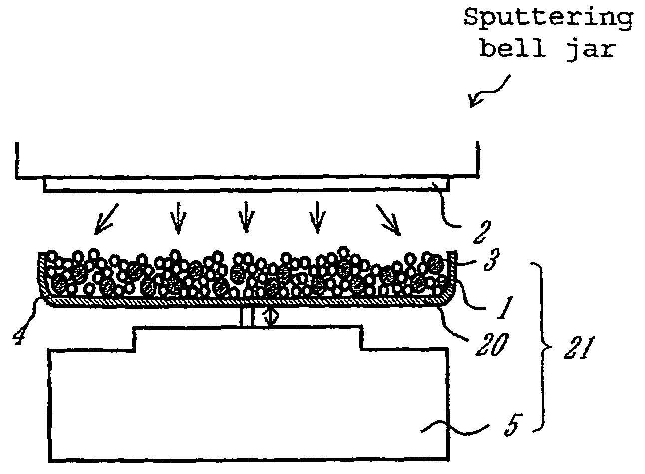
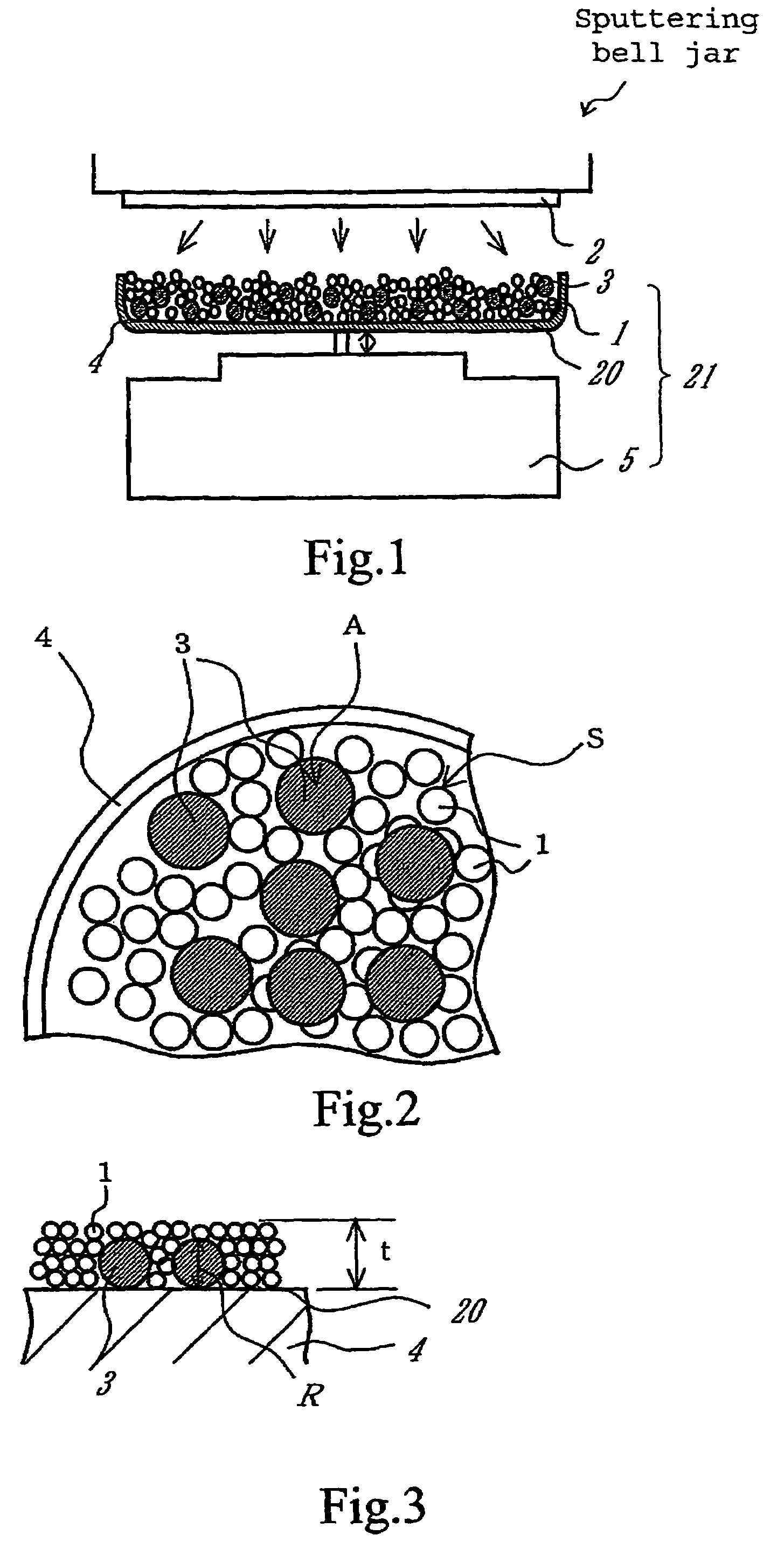
[0100]An apparatus shown in FIG. 1 was assembled from a sputtering target, a vibrator, and a container. The container was charged with a conductive powder and balls. The sputtering target is a platinum disc 100 mm in diameter. The balls are stainless steel balls 3 mm in diameter. The conductive powder is a carbon powder having a specific surface area of 800 m2 / g and an oil absorption value of 360 mL / 100 g. The vibrator generates vibration with an amplitude of ±5 mm and a frequency of 36 Hz.

[0101]The container was charged with the carbon powder (1 g) and the stainless steel balls (35 g). Sputtering was carried out for 30 minutes while the carbon powder and stainless steel balls were being vibrated by the vibrator, with the vacuum chamber supplied with argon (1 Pa) and the target activated by 400W RF. After sputtering, it was found that the carbon powder increased in weight to 1.66 g owing to deposition of platinum (0.66 g) thereon. This implies that the treated carbon powder carries ...

example 2

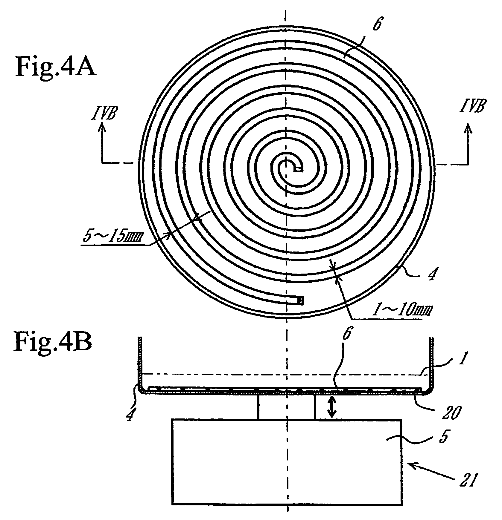
[0104]An apparatus as shown in FIGS. 4A and 4B was assembled from a sputtering target, a vibrator, a container, and a device made of spirally wound wire. The wire is a stainless steel wire 1.6 mm in diameter. The wire is wound at a pitch of about 5 mm to about 10 mm. The outside diameter of the spiral is smaller by about 5 mm than the inside diameter of the container. The conductive powder (carbon powder) mentioned above was placed on the device of spirally wound wire. Being not fixed to the bottom of the container, this device vibrated together with the carbon powder during sputtering to coat the carbon powder with platinum.

[0105]A fuel cell as shown in FIG. 7 was made in the same way as in Example 1 except that the carbon powder was coated with platinum by using the apparatus mentioned above. The obtained fuel cell was tested for output. The output was 120% of that in Example 1.

example 3

[0106]A fuel cell shown in FIG. 7 was made in the same way as in Example 1 except that the carbon powder (which carries platinum) was replaced by the one which has an oil absorption value of 150 mL / 100 g. The obtained fuel cell was tested for output. The output was 65% of that in Example 1.


PUM

PropertyMeasurementUnit
diameteraaaaaaaaaa
frequencyaaaaaaaaaa
specific surface areaaaaaaaaaaa

Abstract

A process for production of conductive catalyst particles, a process for production of a catalyst electrode capable of gas diffusion, an apparatus for production of conductive catalyst particles, and a vibrating apparatus. The process can effectively and uniformly coat the particles of a conductive powder with a catalytic substance.

Description

CROSS REFERENCES TO RELATED APPLICATIONS[0001]The present application claims priority to Japanese Patent Document Nos. P2001-148613 filed on May 18, 2001; and P2002-120822 filed on Apr. 23, 2002, the disclosures of which are herein incorporated by reference.BACKGROUND OF THE INVENTION[0002]The present invention relates to a process for production of conductive catalyst particles, a process for production of a catalyst electrode capable of gas diffusion, an apparatus for production of conductive catalyst particles, and a vibrating apparatus.[0003]It has been usual practice to produce a catalyst electrode capable of gas diffusion from catalyst particles composed of carbon powder (as a conductive powder) and platinum (as a catalyst) supported thereon, in combination with a water-repellent resin (such as fluorocarbon resin) and an ionic conductor, by forming them into a sheet, for example, as disclosed in Japanese Patent Laid-open No. Hei 5-36418 or applying them onto a carbon sheet.[00...

Claims


Application Information

Patent Timeline
Patent Type & Authority Patents(United States)
IPC IPC(8): B01J23/00B01J21/18B01J23/40H01M4/00B01J37/02B01J23/42B01J23/62B01J35/00B01J35/02B01J35/08B01J37/00B01J37/34H01M4/86H01M4/88H01M4/90H01M4/92H01M8/10
CPCB01J21/18B01J23/626B01J35/0033B01J37/347H01M4/8605H01M4/8657H01M4/9075B01J23/40Y02E60/50B01J35/023B01J35/08B01J37/0009B01J37/0232B01J37/0238H01M4/92H01M8/1002H01M8/1007Y02P70/50B01J35/33B01J35/40B01J35/51B01J37/02
Inventor KATORI, KENJIKANEMITSU, TOSHIAKI
Owner SONY CORP
Features
  • Generate Ideas
  • Intellectual Property
  • Life Sciences
  • Materials
  • Tech Scout
  • Unparalleled Data Quality
  • Higher Quality Content
  • 60% Fewer Hallucinations
Learn More