Mounted MEMs optical diagnostic switch

a technology of optical diagnostic switch and optical connector, which is applied in the field of fiber optic communication, can solve the problems of affecting the alignment affecting the yield of the optical connector, so as to achieve the effect of improving yield and simplifying construction

Inactive Publication Date: 2007-11-13
LOCKHEED MARTIN CORP
View PDF12 Cites 8 Cited by
  • Summary
  • Abstract
  • Description
  • Claims
  • Application Information

AI Technical Summary

Benefits of technology

[0013]In another embodiment, the present invention orients the MEMs device parallel to the light source transmission. In this embodiment, the parallel mounted MEMs optical diagnostic switch eliminates the need for the throughbores as mirror placement is controlled within the lithographic capability at the submicron level. The MEMs substrate is disposed in a plane parallel to the light source transmission so that the mirrors are then activated into the light transmission. This embodiment is thus less dependent on the mechanical placement of the MEMs substrate therefore simplifying construction and improving yields.
[0014]The in-line fiber optic diagnostic tool can be used without the mechanical removal of any component of the optical network thus eliminating the danger that the test itself may damage alignment or components. The present invention creates a feedback loop within the existing fiber ribbon. The net result is that an in-line diagnostic capability is performed on power up or whenever requested by the system.

Problems solved by technology

The alignment issue is exacerbated by the tendency to package the optoelectronic devices into an array which transmits multiple signal lines simultaneously.
Fiber optic connectors can fail due to manufacturing errors, environmental fractures and improper handling.
Manufacturing errors include broken fibers inside the ferrule or damage to the fiber buffer.
Fibers may break due to poor construction of the fiber itself.
Air voids in the epoxy that holds the fiber in place may cause the fiber to break free.
Thermal expansion of the epoxy may also break the fiber.
Other manufacturing problems result from poor ferrule end face quality.
If the end face is under or over polished, it may not mate properly with the fiber optic connector.
If these parts are not aligned properly there may be poor signal quality due to the connections.
Failures can also occur due to dropouts created by extreme vibration or shock loads.
When the ferrule end face is damaged by vibrations, the glass fiber may be scratched or damaged leading to high insertion and return losses.
Fiber optic connectors can also fail due to improper cleaning during the assembly process or simply by mating together two connectors that are incompatible.
In addition to failures of connections and cable length, the lasing or detecting device may be the cause of system failure.
These devices are subject to failure due to environmental stress and wear-out.

Method used


Image

  • Mounted MEMs optical diagnostic switch
  • Mounted MEMs optical diagnostic switch
  • Mounted MEMs optical diagnostic switch

Examples


Embodiment Construction

[0026]In the following description of various example embodiments, reference is made to the accompanying drawings which form a part hereof, and in which is shown by way of illustration various manners in which the invention may be practiced. It is to be understood that other embodiments may be utilized, as structural and operational changes may be made without departing from the scope of the present invention.

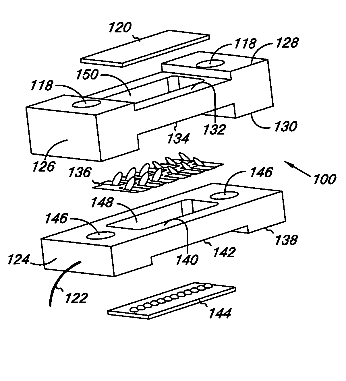
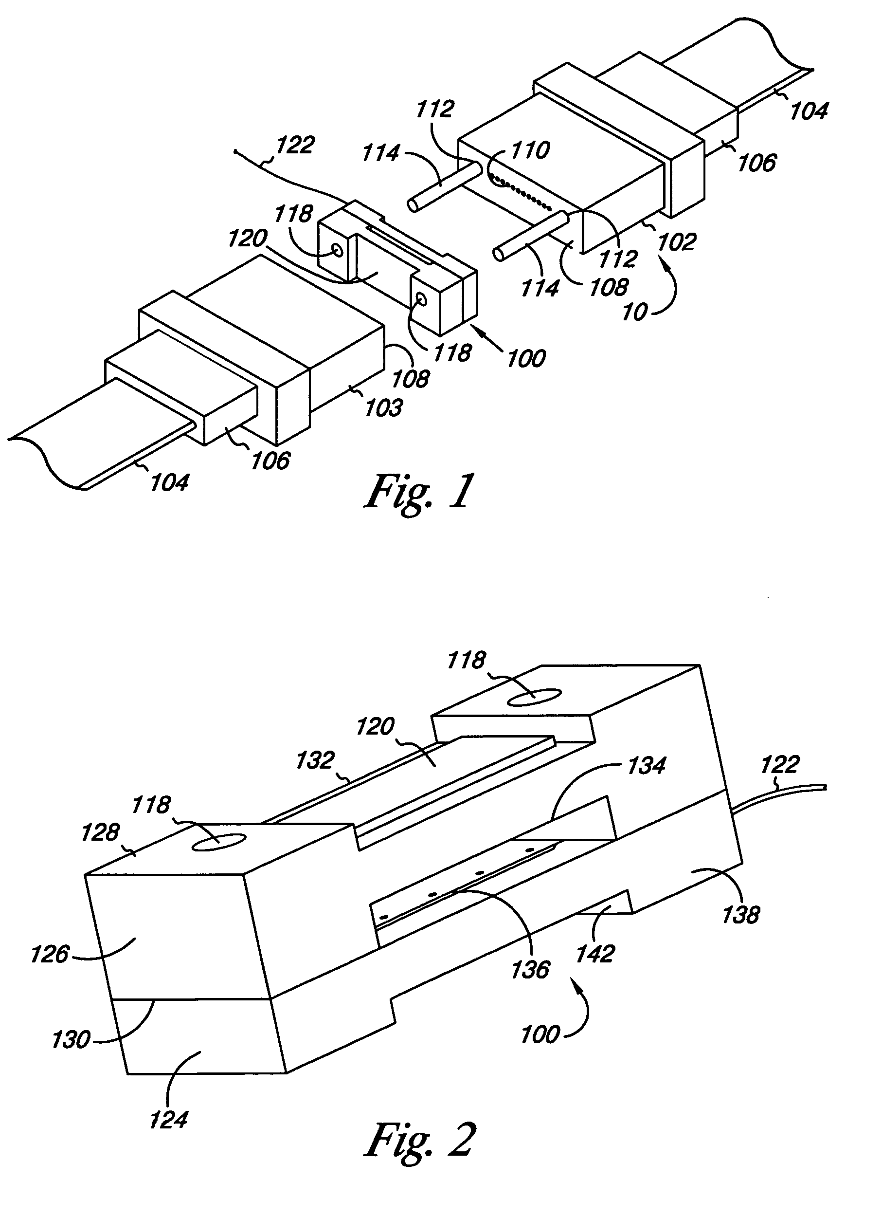
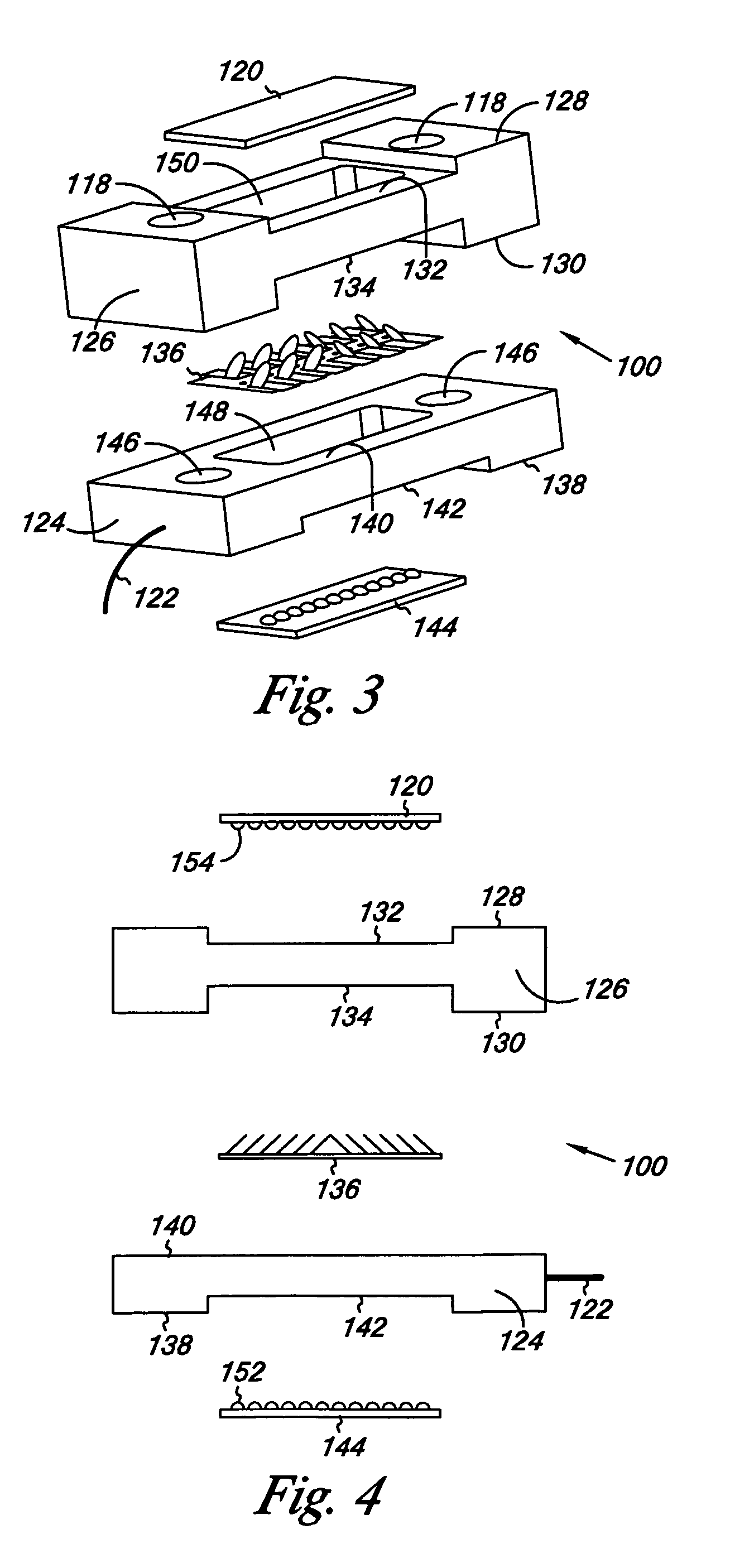
[0027]Generally, the present invention is a switch that provides an in-line diagnostic tool for directing light from one or a plurality of light sources to one or a plurality of light collectors by activating a feedback loop through the use of micro electro mechanical systems (MEMS). The present invention can be automatically activated to an active mode at power up or selectively thereafter. When in the passive mode, the present invention retracts away from the optical path so as not to interfere with normal operations.

[0028]As illustrated in FIG. 1, the in-line diagnostic tool...


PUM


Abstract

A parallel mounted MEMs optical diagnostic switch disposed within an optical connector for directing optical signals from one or a plurality of light sources to one or a plurality of light collectors by activating a feedback loop through the use of micro electro mechanical systems (MEMS). The present invention includes one or more mirrors mounted parallel to the path of optical transmission through the tool. The mirrors and can be automatically activated at power up or selectively thereafter for detecting faults in any upstream fiber optic component. When in the passive mode, the present invention retracts away from the optical path so as not to interfere with normal system operations.

Description

FIELD OF THE INVENTION[0001]This invention generally relates to the art of fiber optic communications and particularly to a system to improve the health and maintenance of optical signal transmissions through fiber optic pathways by inserting a parallel mounted MEMs optical diagnostic switch between conventional MT connectors for selectively creating a feedback loop to diagnose the condition of each optoelectronic module or the condition of the fiber optic path.BACKGROUND OF THE INVENTION[0002]Fiber optic transmission systems typically utilize an optoelectronic source such as a LED or a vertical cavity surface emitting laser (VCSEL) to generate optical signals for communication purposes. The optical signals are transmitted along optical glass fibers to a receiver diode or similar communications device where the optical signals are converted to electrical signals. For competitive reasons, optical networks support an ever increasing menu of products which require high bandwidth and ve...

Claims


Application Information

Patent Timeline
Patent Type & Authority Patents(United States)
IPC IPC(8): G02B6/35
CPCG02B6/3885G02B6/3582G02B6/3512G02B6/3546G02B6/385G02B6/3562
Inventor THORSON, KEVIN J.KRYZAK, CHARLES J.LEININGER, BRIAN S.STEVENS, RICK C.
Owner LOCKHEED MARTIN CORP
Why Eureka
Try Eureka