Sub-optimal iterative receiver method and system for a high-bit-rate CDMA transmission system

a transmission system and receiver technology, applied in the field of suboptimal iterative receiver methods and systems for highbitrate cdma transmission systems, can solve the problems of serious deformation of the performance of the rake receiver, interference between symbols of the same transmitted signal, and the inability to meet the high-bit-rate packet service. , to achieve the effect of low spreading factor, high order modulation, and close to optimum performan

Active Publication Date: 2007-11-20
FRANCE TELECOM SA
View PDF19 Cites 40 Cited by
  • Summary
  • Abstract
  • Description
  • Claims
  • Application Information

AI Technical Summary

Benefits of technology

[0027]An object of the present invention is to solve these problems in order to propose a reception method and a receiver structure that are relatively simple, that have close to optimum performance, and that use high order modulation combined with a low spreading factor. This object is achieved by providing a method of receiving a signal transmitted on a multipath transmission channel using a spread spectrum technique with a low spreading factor, said signal being transmitted in the form of sequences of coded binary symbols comprising both predefined pilot symbols and data symbols multiplied by a spreading sequence, said method including a step of determining a channel estimate using received predefined pilot symbols.

Problems solved by technology

In radio transmission, the form of the medium between the sender and the receiver of a radio signal interferes with transmission and leads to propagation along multiple paths caused by reflections at different points along the radio channel, especially in an urban environment.
Although the CDMA technique would seem to be very suitable for real time low-bit-rate services, it appears to be unsuitable for high-bit-rate packet services because the performance of the rake receiver is based on cross-correlation and autocorrelation properties of the spreading sequences, which improves as the length of the spreading sequence, and thus of the spreading factor, is increased.
The spreading sequence becomes shorter and the cross-correlation and autocorrelation properties of the spreading sequences are therefore degraded, leading to interference between symbols of the same transmitted signal.
As a result of this, the performance of the rake receiver is seriously degraded for spreading factors less than 8, especially if the type of modulation used has a large number of states.
Thus rake receivers on their own are found to be a very unsuitable response to the requirements of high-bit-rate mobile telephony.
At present it is virtually impossible to use optimum detection and encoding techniques, as this leads to very high calculation complexity, especially if the transmission channels have an impulse response that is too long, as is the case in an urban environment.
Note that interuser interference on downlinks is caused by multipath propagation in the channels, given that the spreading sequences of different users are mutually orthogonal.
However, the complexity of that solution increases exponentially with the spreading of the time delays in the same channel and with the size of the modulation constellation employed.
Thus it cannot be applied to all UMTS services.
Furthermore, that solution does not take into account the degraded performance caused by incorrect channel estimation and channel coding.
Furthermore, it does not offer a flexible or weighted output algorithm.
In TDMA systems, that technique has the drawback of being sensitive to error propagation, which necessitates prefiltering.
However, the above solution has not been transposed to CDMA systems, and further introduces undue complexity of the receiver, of the order of ML, where M is the number of points of the modulation constellation and L is the number of echoes in the propagation channel taken into account.
Moreover, it does not address the channel estimation problem.
However, compared to the turbo-detection technique, the turbo-equalization technique degrades performance in a way that is strongly dependant on the equalization technique employed for the first iteration.
That technique cannot be transposed to CDMA systems since it is based on filtering techniques that cannot be applied if the channel varies independently from one transmitted symbol to another.

Method used


Image

  • Sub-optimal iterative receiver method and system for a high-bit-rate CDMA transmission system
  • Sub-optimal iterative receiver method and system for a high-bit-rate CDMA transmission system
  • Sub-optimal iterative receiver method and system for a high-bit-rate CDMA transmission system

Examples


Embodiment Construction

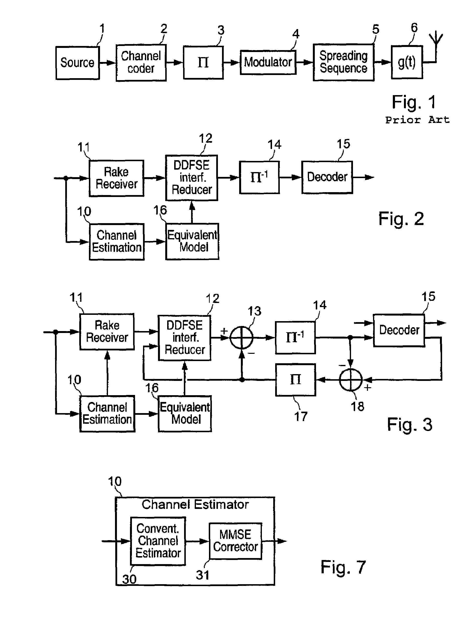
[0061]FIG. 1 shows a prior art CDMA transmitter, comprising a signal source 1 supplying sequences of τ0 binary symbols u1τ0={u1, . . . , uτ0}T and a channel encoder 2 that supplies a coded sequence c1τ0={c1, . . . , cτ0}T.

[0062]Each data symbol un={un,1, . . . , un,k0)T contains k0 bits and each symbol cn={cn,1, . . . , cn,n0}T contains n0 bits. The coded bits are interleaved by an interleaver 3 and padded out to correspond to a predetermined transmission format, i.e. frames of length τ containing pilot symbols to allow a receiver to carry out channel estimation. The resulting bits are grouped into symbols of type ak=(ak,l, . . . , ak,q) containing q bits before they are fed to a modulator 4 performing M-th order phase-shift keying (M-PSK), MAQ16 or MAQ64, which supplies a corresponding modulated symbol s(k).

[0063]The signal s(k) is then multiplied at 5 by a predefined spreading sequence c(q) for the transmission in question, the resulting signal being passed through a raised cosine...


PUM


Abstract

A reception method and receiver structure that are relatively simple, that have close to optimum performance, and that use high order modulation combined with a low spreading factor are disclosed. The method receives a signal transmittal in the form of sequences of coded binary symbols comprising both predefined pilot symbols and date symbols multiplied by a spreading sequence. The method also includes a step of determining a channel estimate using received predefined pilot symbols. A system for receiving a signal transmitted on a multipath transmission channel using a spread spectrum technique and low spreading factor is also disclosed.

Description

[0001]This application claims priority to PCT Application No. PCT / FR02 / 02848 filed Aug. 9, 2002 and French Application No. 0111549 filed Sep. 6, 2001.[0002]The present invention relates to a high-bit-rate radio receiver method and system for receiving signals in a radio system utilizing the code division multiple access (CDMA) technique.BACKGROUND OF THE INVENTION[0003]Information is transmitted in mobile telephone systems using a multiple access technique. Some systems use frequency division multiple access (FDMA) and time division multiple access (TDMA), users of the network being distinguished from each other by the respective frequency used and by the information to be transmitted being delivered in time slots assigned to each user. In systems based on code division multiple access (CDMA), users communicate with each other using the same radio frequency band. To be able to distinguish users from one another, each is assigned a respective spreading code for the whole duration of ...

Claims


Application Information

Patent Timeline
Patent Type & Authority Patents(United States)
IPC IPC(8): H04B1/00H03M13/27H03M13/41H04B1/707H04L1/00H04L25/02H04L25/03H04L25/06
CPCH04B1/712H04L25/0236H04L25/06H04B2201/70701H04L25/025H04L25/03235H04L25/0242
Inventor VISOZ, RAPHAELBOUJEMAA, HATEM
Owner FRANCE TELECOM SA
Why Eureka
Try Eureka