Switching power supply circuit

a power supply circuit and circuit technology, applied in the direction of packaging foodstuffs, instruments, packaged goods, etc., can solve the problems of not performing zvs properly, zvs is not easily obtained, zvs is not performed properly, etc., to achieve the effect of eliminating abnormal operation, improving power conversion efficiency, and being convenient to put to us

Inactive Publication Date: 2007-11-27
SONY CORP
View PDF20 Cites 42 Cited by
  • Summary
  • Abstract
  • Description
  • Claims
  • Application Information

AI Technical Summary

Benefits of technology

[0050]Thus, the present invention eliminates the above-described abnormal operation in a voltage resonant converter provided with a secondary side series resonant circuit. Therefore, the voltage resonant converter provided with the secondary side series resonant circuit is easily put to practical use. In addition, power conversion efficiency is improved by eliminating the abnormal operation.

Problems solved by technology

The coupling coefficient k at this level may be considered to represent loose coupling, and therefore a state of saturation is not easily obtained.
This operation is abnormal operation in which ZVS is not performed properly.
That is, it is known that the voltage resonant converter having the secondary side series resonant circuit as shown in FIG. 8 performs abnormal operation in which ZVS is not performed properly at medium load.
This increases a switching loss, and results in a factor in decreasing power conversion efficiency.
At any rate, abnormal operation as described above causes a shift in a phase-gain characteristic of a constant-voltage control circuit system, for example, thus resulting in a switching operation in an abnormal oscillation state.
Thus, in a present situation, there is a strong perception that it is in actuality difficult to put the power supply circuit of FIG. 8 to practical use.

Method used


Image

  • Switching power supply circuit
  • Switching power supply circuit
  • Switching power supply circuit

Examples


first embodiment

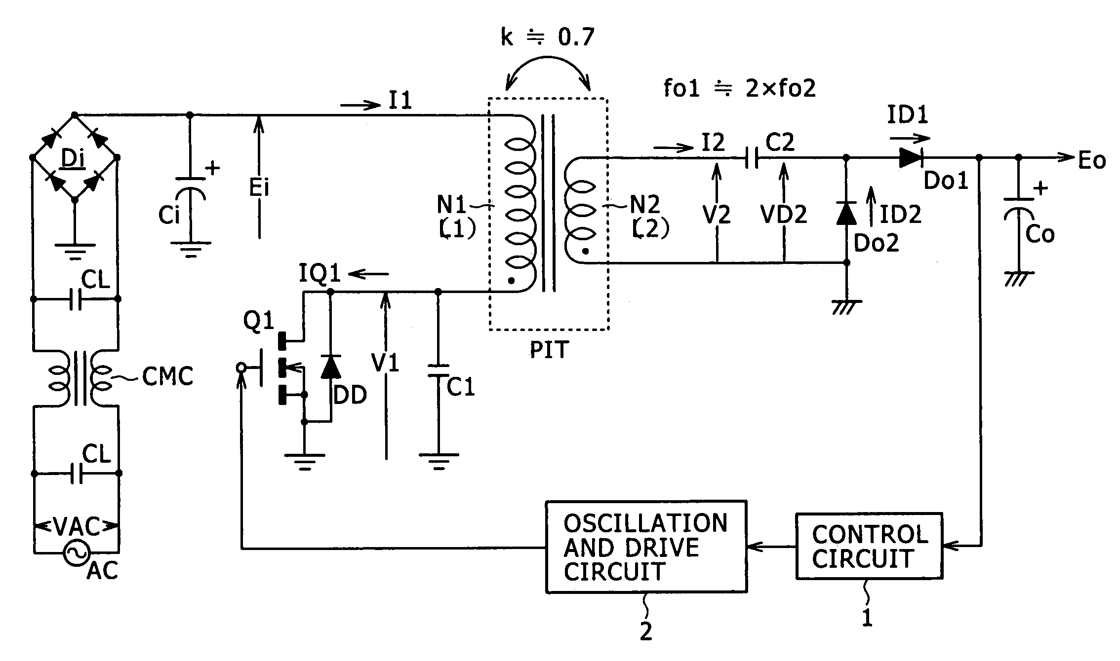
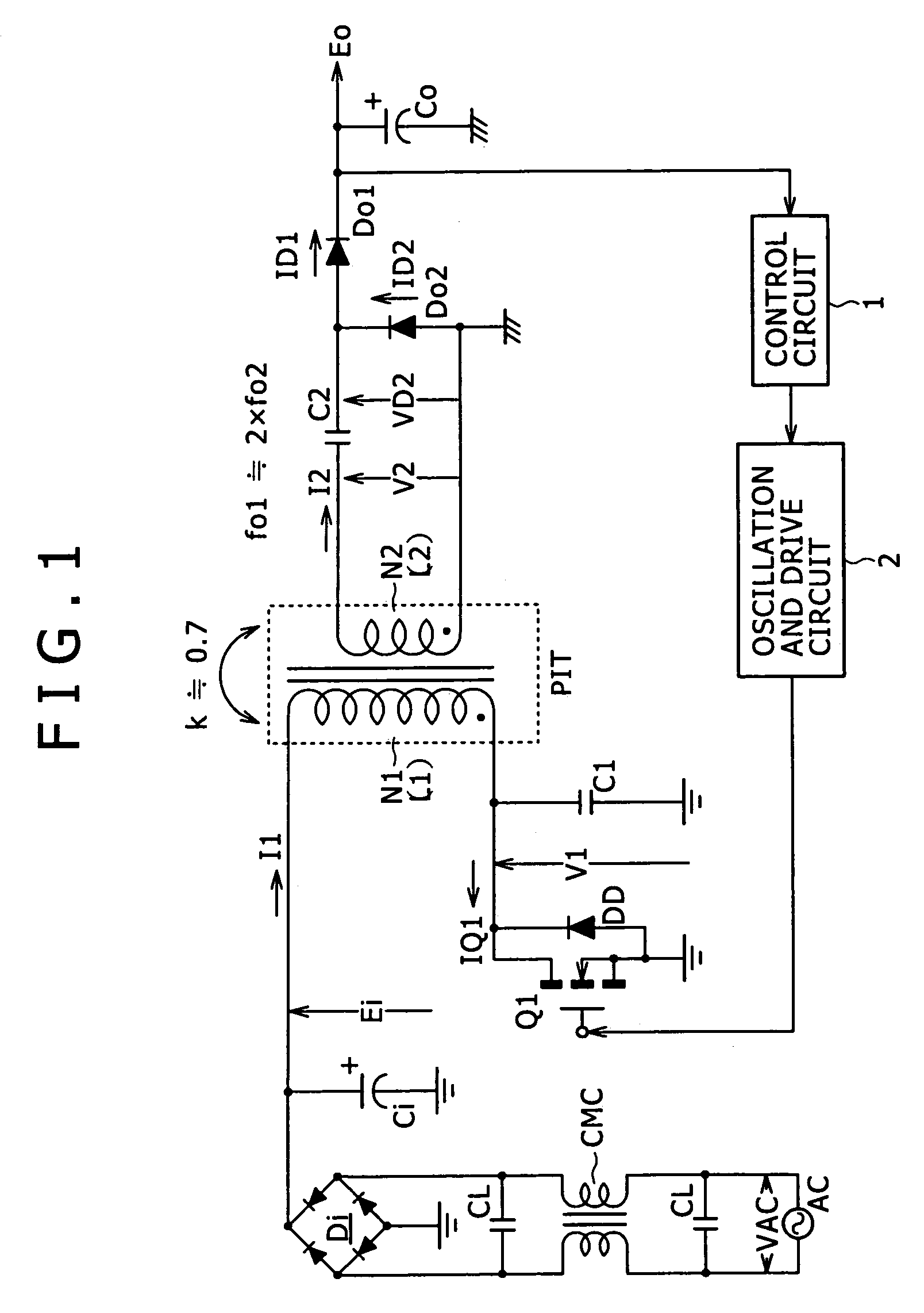
[0063]A circuit diagram of FIG. 1 shows an example of configuration of a power supply circuit as the best mode (an embodiment) for carrying out the invention. The power supply circuit shown in this figure employs a fundamental configuration of a voltage resonant switching converter using a single-ended system.

[0064]In the switching power supply circuit shown in this figure, a set of common mode choke coils CMC and two across capacitors CL are inserted in the line of a commercial alternating-current power supply AC, as shown in the figure. The common mode choke coils CMC and the across capacitors CL and CL form a noise filter for eliminating common mode noise superimposed on the line of the commercial alternating-current power supply AC.

[0065]An alternating input voltage VAC is rectified by a bridge rectifier circuit Di. A smoothing capacitor Ci is charged with the rectified output of the bridge rectifier circuit Di. Thereby a rectified and smoothed voltage Ei is obtained as a volta...

second embodiment

[0138]FIG. 6 shows an example of configuration of a power supply circuit according to a Incidentally, in FIG. 6, the same parts as in FIG. 1 are identified by the same reference numerals, and description thereof will be omitted.

[0139]The power supply circuit shown in FIG. 6 has a voltage doubler full-wave rectifier circuit as a secondary side rectifier circuit.

[0140]A secondary winding N2 in the voltage doubler full-wave rectifier circuit is provided with a center tap to be divided into two secondary winding parts N2A and N2B with the center tap as a boundary. The same predetermined number of turns is set for the secondary winding parts N2A and N2B.

[0141]A secondary side series resonant capacitor C2A is connected in series with an end part on the secondary winding part N2A side of the secondary winding N2. A secondary side series resonant capacitor C2B is connected in series with an end part on the secondary winding part N2B side of the secondary winding N2. Thereby, a first second...

third embodiment

[0157]FIG. 7 is a circuit diagram showing an example of configuration of a power supply circuit according to a Incidentally, in FIG. 7, the same parts as in FIG. 1 and FIG. 6 are identified by the same reference numerals, and description thereof will be omitted.

[0158]The power supply circuit shown in FIG. 7 has a bridge full-wave rectifier circuit including a bridge rectifier circuit formed by four rectifier diodes Do1, Do2, Do3, and Do4 as a secondary side rectifier circuit for an isolated converter transformer PIT. This bridge rectifier circuit is formed such that a point of connection between the anode of the rectifier diode Do1 and the cathode of the rectifier diode Do2 is a positive electrode input terminal, a point of connection between the cathode of the rectifier diode Do1 and the cathode of the rectifier diode Do3 is a positive electrode output terminal, a point of connection between the anode of the rectifier diode Do3 and the cathode of the rectifier diode Do4 is a negat...


PUM


Abstract

An abnormal operation in which a current flows through a switching device before the end of an off period of the switching device at medium load is eliminated by setting the coupling coefficient of an isolated converter transformer to about 0.7 or lower. A primary side parallel resonance frequency and a secondary side series resonance frequency are set so as to obtain favorable power conversion efficiency characteristics.

Description

CROSS-REFERENCE TO RELATED APPLICATIONS[0001]The present application claims priority from Japanese Patent Application No. JP 2005-016758 filed on Jan. 25, 2005, the disclosure of which is hereby incorporated by reference herein.BACKGROUND OF THE INVENTION[0002]The present invention relates to a switching power supply circuit including a voltage resonant converter.[0003]As so-called soft-switching power supply of a resonant type, a current resonant type and a voltage resonant type are widely known. In a present situation, a current resonant converter having two switching devices coupled by a half-bridge coupling system is in wide use because such a current resonant converter is easily put to practical use.[0004]However, the characteristics of a high withstand voltage switching device, for example, are now being improved, and therefore the problem of withstand voltage in putting a voltage resonant converter to practical use is being cleared up. In addition, a voltage resonant converte...

Claims


Application Information

Patent Timeline
Patent Type & Authority Patents(United States)
IPC IPC(8): H02M3/335
CPCH02M3/33507H02M3/3385Y02B70/16Y02B70/1433H02M2001/0032H02M1/0032Y02B70/10A61J1/05A61M35/003
Inventor YASUMURA, MASAYUKI
Owner SONY CORP
Why Eureka
Try Eureka