Spectroscopic apparatus

a spectroscopic apparatus and a technology of spectroscopic instruments, applied in the field of spectroscopic instruments, can solve the problems of inability to meet the demand of reducing the size of the spectroscope, the size of the optical system is increased, and the number of grooves cannot be increased, so as to achieve compact size and large angular dispersion

Inactive Publication Date: 2007-12-04
FUJITSU LTD
View PDF12 Cites 134 Cited by
  • Summary
  • Abstract
  • Description
  • Claims
  • Application Information

AI Technical Summary

Benefits of technology

[0018]The present invention has been made in view of the above described points, and an object thereof is to provide a spectroscopic apparatus which is compact in size and performs high-precision light-splitting with a large angular dispersion.

Problems solved by technology

However, in actuality, due to restrictions on machining, there is a limit to increasing the number of grooves.
In spectroscopes using the diffraction grating described above, an increase in the resolution results in the increased size of the optical system (optics constituting an optical path over which light generated by a light source travels to a photodetector), which makes it impossible to comply with the demand of reduction of the size of spectroscopes.
However, it is impossible to apply the proposed VIPA as it is to a spectroscope as an optical measurement apparatus.
However, as the optical measurement apparatus, the VIPA-based spectroscope is required to receive a light component (optical spectrum) obtained by splitting one wavelength (band), which makes it impossible to use such a VIPA-based spectroscope as used in WDM as it is, for the spectroscopic apparatus for optical measurement.

Method used


Image

  • Spectroscopic apparatus
  • Spectroscopic apparatus
  • Spectroscopic apparatus

Examples


first embodiment

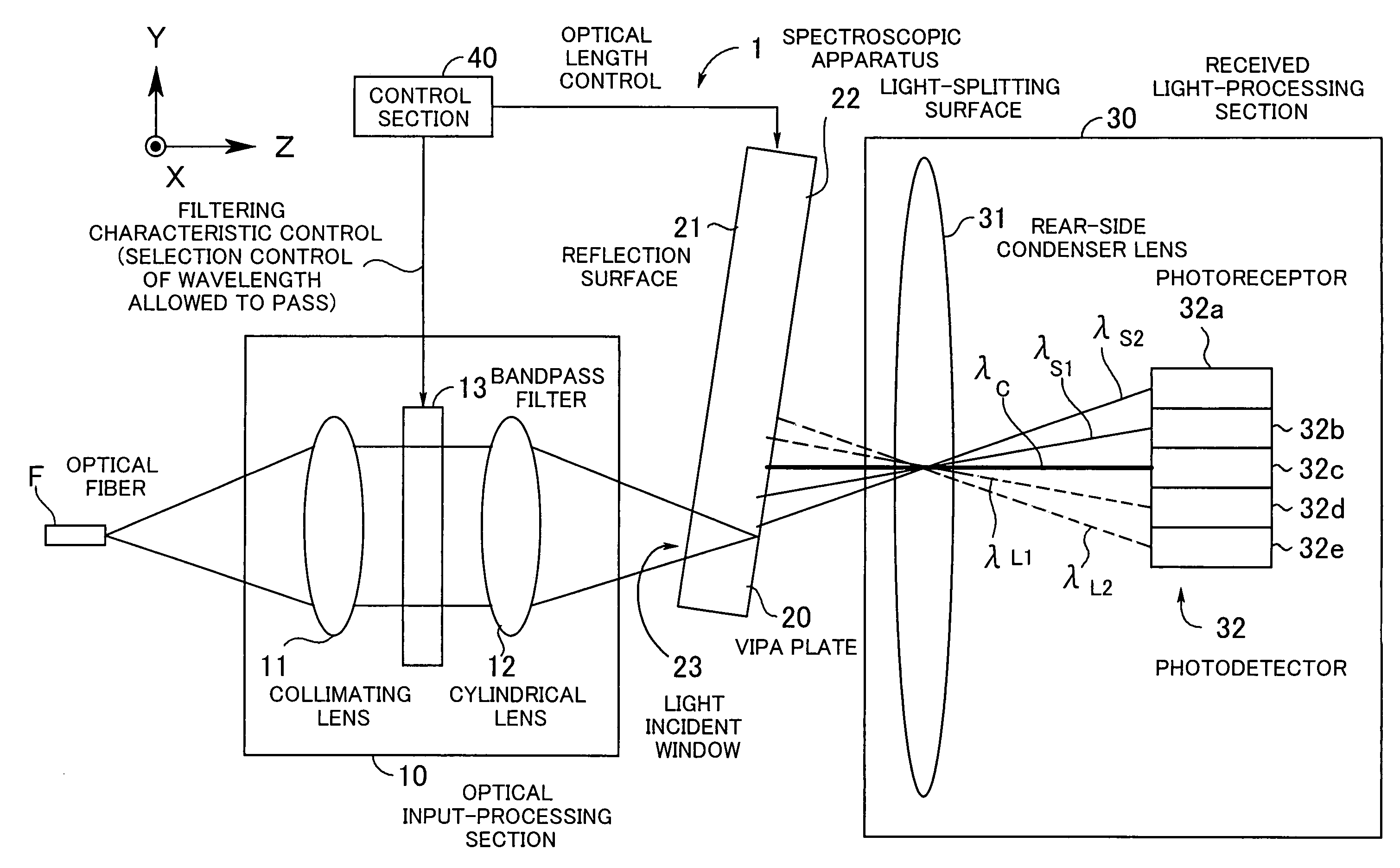
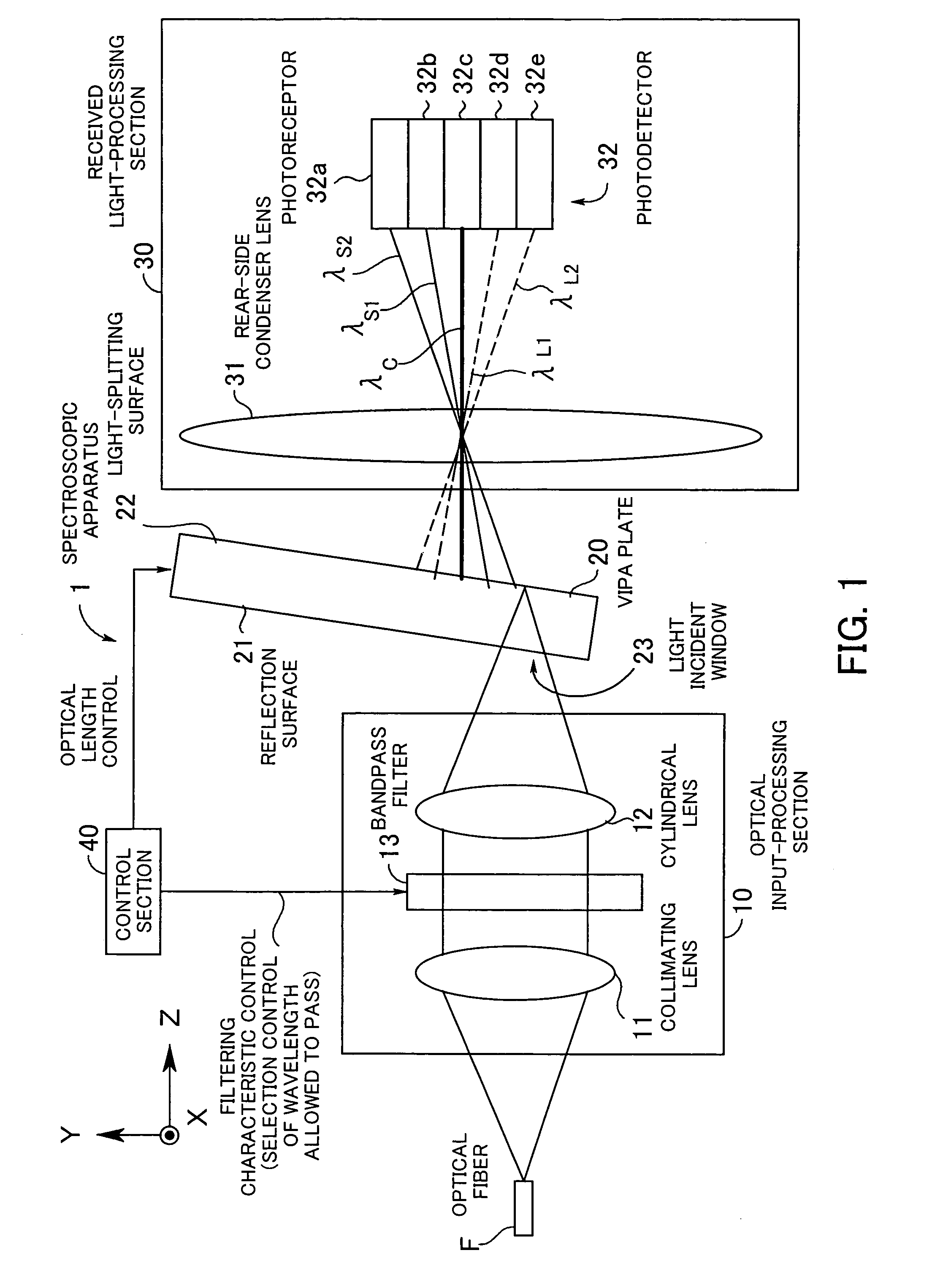
[0061]FIG. 1 is a diagram showing the basic arrangement of a spectroscopic apparatus according to the present invention, which is useful in explaining the principles of the present invention. The spectroscopic apparatus 1 is an apparatus associated with spectroscopic measurement in general, in which spectroscopy is performed, and is comprised of an optical input-processing section 10, an optic 20, a received light-processing section 30, and a control section 40. The optic 20 is hereinafter referred to as “the VIPA plate 20”.

[0062]The optical input-processing section 10 is comprised of a lens 11 (hereinafter referred to as “the collimating lens 11”), a front-side condenser lens 12 (hereinafter referred to as “the cylindrical lens 12”), and a bandpass filter 13, and the bandpass filter 13 is disposed between the collimating lens 11 and the cylindrical lens 12. Further, the received light-processing section 30 is comprised of a rear-side condenser lens 31 (hereinafter, simply referred ...

second embodiment

[0143]Next, a detailed description will be given of a first form of the received light-processing section 50. In the first form of the received light-processing section 50, the light-splitting section 53 is comprised of two diffraction gratings. FIGS. 28 and 29 show a spectroscopic apparatus 1a-1 in which the first form of the received light-processing section 50 is employed. FIG. 28 is a diagram of the spectroscopic apparatus 1a-1 as viewed from the X direction, while FIG. 29 is a diagram of the received light-processing section 50 of the spectroscopic apparatus 1a-1 as viewed from the Y direction.

[0144]The light-splitting section 53-1 includes two transmission diffraction gratings 53a and 53b which forms a diffraction grating pair (grooves in the gratings are opposed to each other). The diffraction grating 53a has a function of separating wavelength-beams aligned according to period in the X direction from each other. The diffraction grating 53b has grooves thereof opposed to the...


PUM

PropertyMeasurementUnit
reflectivityaaaaaaaaaa

Abstract

A spectroscopic apparatus which is compact in size and performs high-precision light-splitting with a large angular dispersion. An optical input-processing section outputs a filtered transmitted light, using a bandpass filter that transmits only wavelength bands at one period of an input light, and collects the filtered transmitted light to generate a collected beam. An optic includes a first reflection surface and a second reflection surface which are high but asymmetric in reflectivity, and causes the collected beam incident thereon to undergo multiple reflections within an inner region between the first reflection surface and the second reflection surface, to thereby cause split beams to be emitted via the second reflection surface. A received light-processing section performs received light processing of the beams emitted from the optic. A control section variably controls at least one of a filter characteristic of the bandpass filter and an optical length through the optic.

Description

BACKGROUND OF THE INVENTION[0001](1) Field of the Invention[0002]This invention relates to a spectroscopic apparatus, and more particularly to a spectroscopic apparatus associated with spectroscopic measurement in general, in which spectroscopy is performed.[0003](2) Description of the Related Art[0004]Spectroscopy means operation of splitting light according to wavelength or frequency, and is utilized for optical measurement in analyzing and measuring the structure of a substance, etc. Spectrometry is widely used in various fields, including medicine and engineering.[0005]Spectrometry includes a pre-splitting method in which light having a continuous spectrum is split and then irradiated onto a sample, and a post-splitting method in which light having a continuous spectrum is irradiated onto a sample without splitting the same and the resulting transmitted / reflected light is split. In both of the methods, the spectroscopic characteristics of a substance can be represented by a spec...

Claims


Application Information

Patent Timeline
Patent Type & Authority Patents(United States)
IPC IPC(8): G01B9/02G02B27/00G01J3/12G01J3/18G01J3/26G01J3/28G02B6/34G02B26/00G02B27/14G02F1/01G02F1/03
CPCG01J3/18G01J3/26G01J3/2803G02B6/4246G02B27/0087G02B27/1086G02B27/144G01J3/0208G02F2203/055G01J2003/1247G02B6/29311G02B6/29358G02B6/29373G02B6/29395G02F1/0147G02F1/03G02F2201/17G01J3/0286
Inventor IZUMI, HIROTOMONAGAEDA, HIROSHIMITAMURA, NOBUAKI
Owner FUJITSU LTD
Why Eureka
Try Eureka