Valve mechanism for infusion fluid systems

a valve mechanism and fluid system technology, applied in the direction of filtration separation, multi-stage water/sewage treatment, separation process, etc., can solve the problems of contaminated final sterility filter, no prevention mechanism, and no cost comparison,

Inactive Publication Date: 2007-12-11
LAMBDA INVESTORS
View PDF26 Cites 49 Cited by
  • Summary
  • Abstract
  • Description
  • Claims
  • Application Information

AI Technical Summary

Benefits of technology

[0012]The present invention provides a method and an apparatus that prevents retrograde flow of fluid, e.g., blood products (i.e., blood proteins), into a source of sterile substitution fluid. The apparatus of the present invention includes a controllable valve mechanism having a valve member that is placed on a section of a conduit which carries sterile substitution fluid to an extracorporeal circuit. In one embodiment, the controllable valve member is in the form of a pinch valve which is placed along a section of flexible tubing. Control over the pinch valve is based on a control unit, e.g., a feedback control loop, using fluid pressures that are sensed upstream and downstream of the pinch valve. The pinch valve is preferably opened only when the upstream pressure is greater than the downstream pressure. This assures that the substitution fluid flows only in a single direction (i.e. from the higher pressure substitution fluid source to the lower pressure extracorporeal circuit) when the pinch valve is in the open position.

Problems solved by technology

This results in a greater cost when compared to using a standard intravenous (IV) administration set.
The '829 patent does not address any means of preventing the final sterilizing filter (located between the venous drip chamber and the substitution pump) from being contaminated by blood products (red cells, proteins, etc.).
Though the infusion tubing segment between the final filter and the venous chamber may include a microfilter (e.g., 0.22 micron nominal pore size), it is understood by those skilled in the art that this microfilter does not prevent the final sterility filter from being contaminated by blood proteins when blood backs up into the infusion tubing set that is attached to the final sterility filter.
The disadvantage of this system is that the system requires a special infusion tubing set that includes a dedicated pump segment for its operation.
This infusion tubing set is accordingly more complex and costly than a standard IV administration set (that is typically used to prime the circuit with saline or for infusing sterile fluid into the blood circuit during dialysis treatment).

Method used


Image

  • Valve mechanism for infusion fluid systems
  • Valve mechanism for infusion fluid systems
  • Valve mechanism for infusion fluid systems

Examples


first embodiment

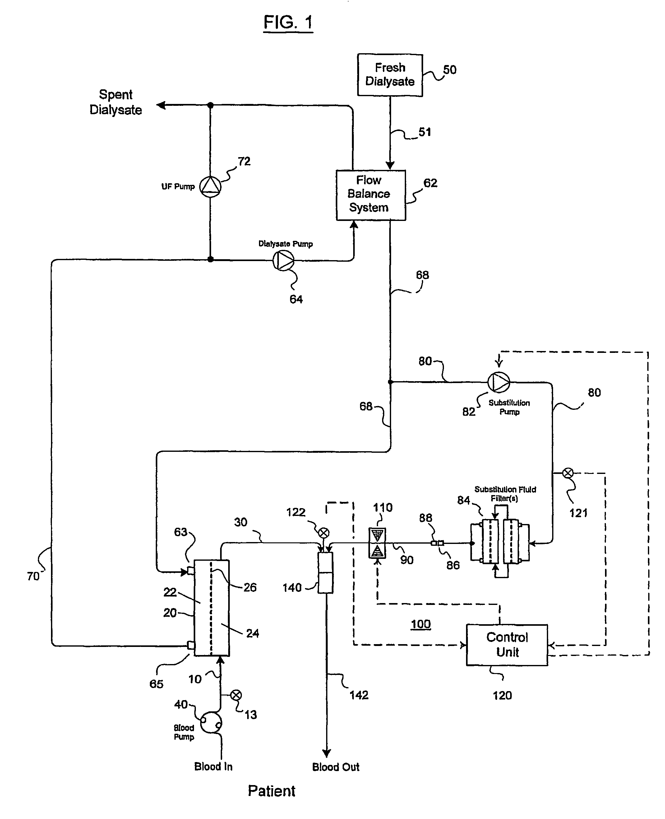
[0038]In this embodiment, the first monitoring device 13 acts as a downstream sensor for monitoring the fluid pressure at downstream locations relative to the pinch valve 110. Preferably, the arterial pressure is also measured at the location of the first monitoring device 13. As with th first embodiment, the fluid pressure of the substitution fluid is continuously monitored at the upstream sensor 121.

[0039]In this embodiment, the second monitoring device 122 (i.e. the second sensor) does not serve as a downstream sensor for monitoring the flow pressure of the substitution fluid after the fluid passes through the pinch valve 110 but rather acts as a venous pressure sensor. Sensor 122 thus measures the pressure of the fluid as it enters the chamber 140. Chamber 140 is therefore not a mixing chamber but rather is a chamber which receives the fluid from the dialyzer cartridge 20 and is coupled to conduit 142 which delivers the filtered blood back to the patient. Alternatively, chamber ...
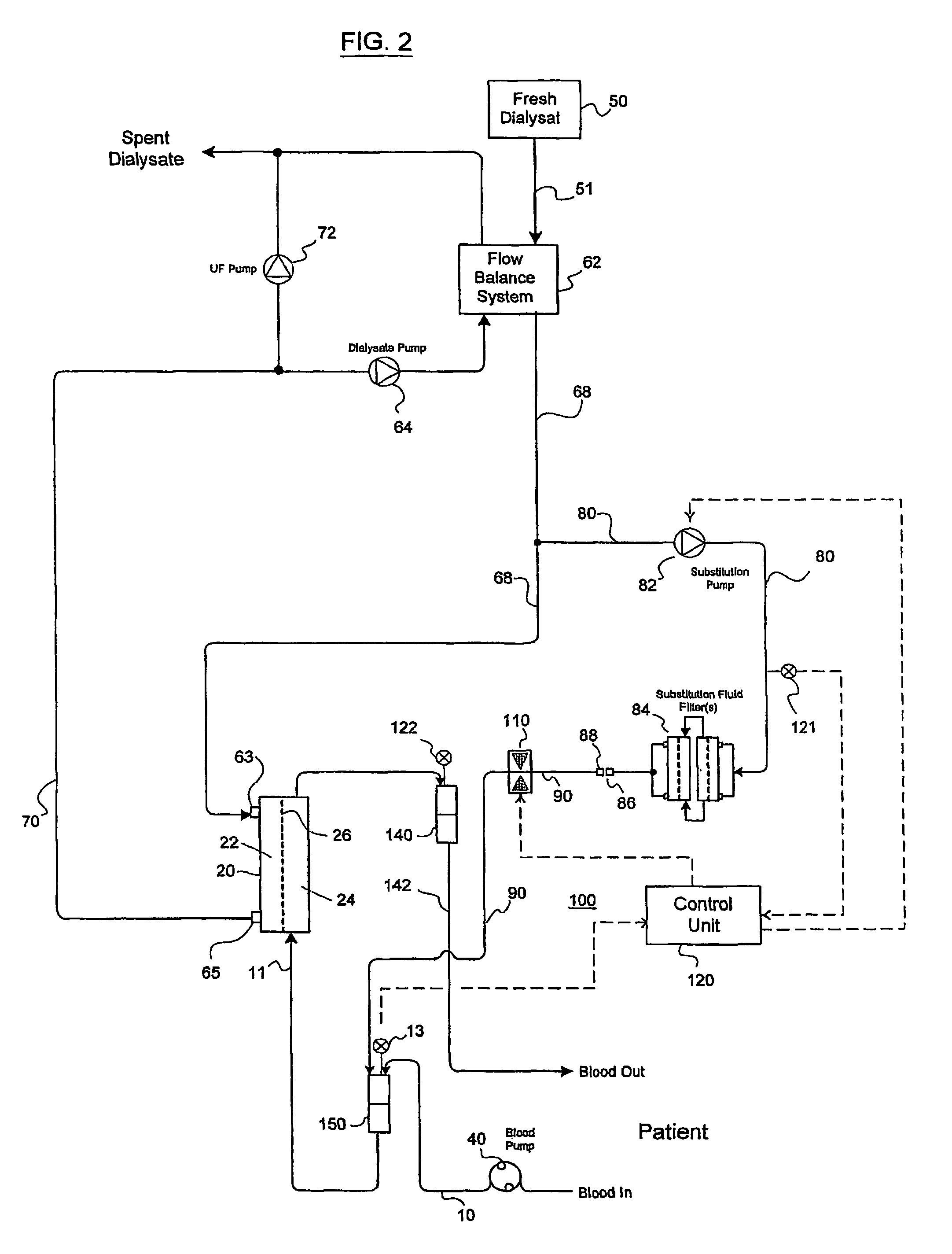
second embodiment

[0041]Advantageously, the second embodiment prevents retrograde blood flow from the chamber 150 into the flexible tubing 90 which is connected thereto in a pre-dilution scheme. In each embodiment of the present invention, the valve mechanism 100 is easily incorporated into a variety of existing hemodiafiltration apparatus or the like.

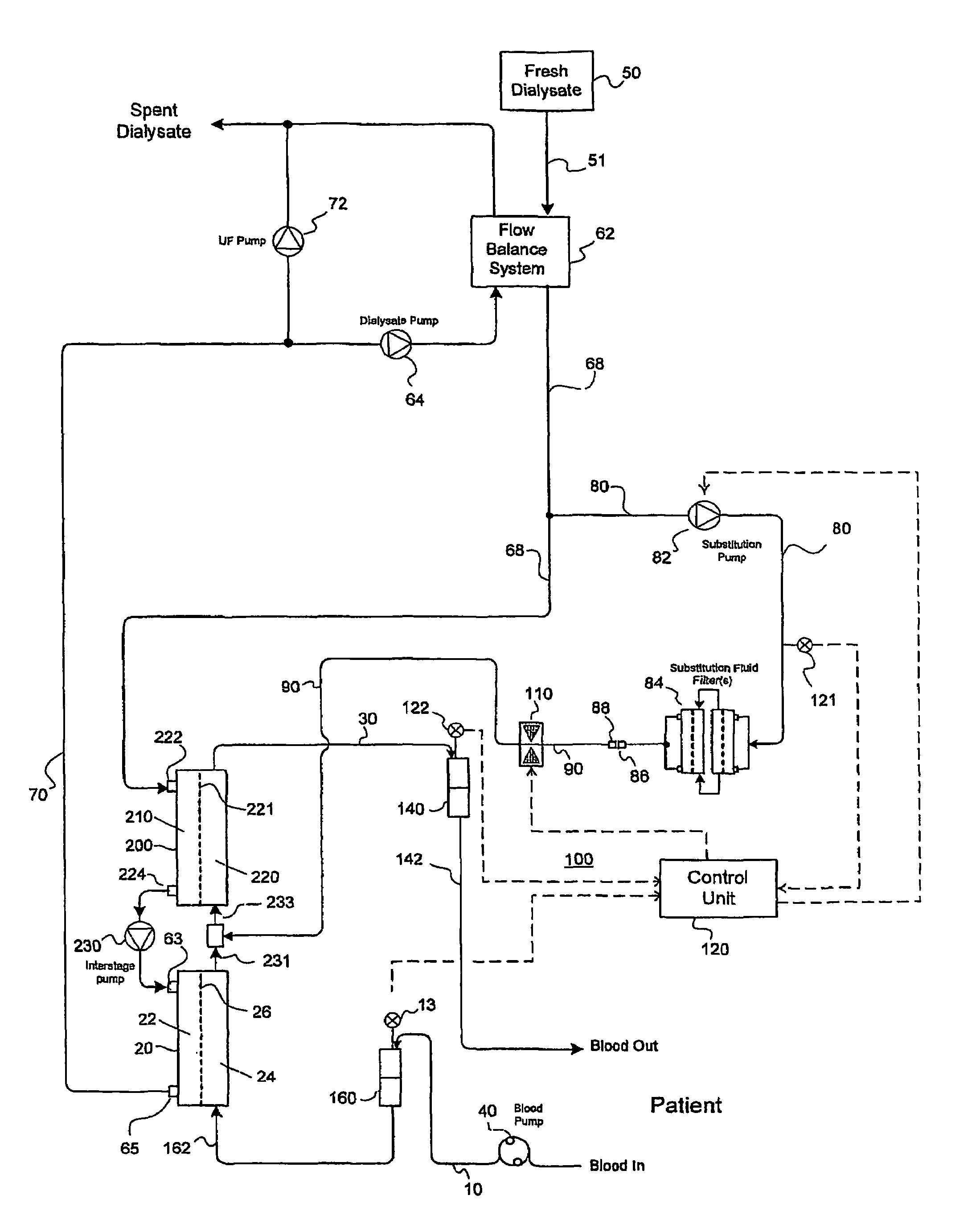
[0042]Reference is made to FIG. 3 which schematically illustrates a third embodiment of the present invention. In this third embodiment, the present invention is shown as being part of a substitution fluid delivery system typical of a hemodiafiltration system having first and second dialyzer cartridges 20, 200 in which the sterile substitution fluid is introduced at a location between the first and second dialyzer cartridges 20, 200. The substitution fluid can be introduced (i.e., through a connector) into a conduit that extends between and links the first and second dialyzer cartridges 20, 200 or the substitution fluid can be introduced into a chamber ...

third embodiment

[0043]In this third embodiment, blood is propelled through the extracorporeal circuit using the blood pump 40. The blood flows through the bloodline 10 to the chamber 160. The arterial pressure is measured at the first monitoring device 13 and the measured information is continuously transmitted to the control unit 120. A conduit (bloodline) 162 fluidly connects the chamber 160 to the first dialyzer cartridge 20. The second dialyzer cartridge 200 is similar to the first dialyzer cartridge 20 and may be of any type suitable for hemodialysis, hemodiafiltration, hemofiltration, or heomoconcentration as is the case with the first dialyzer cartridge 20. More specifically, the second dialyzer cartridge 200 has a dialysate compartment 210 and a blood compartment 220 defined by a semipermeable membrane 221. The second dialysate cartridge 200 also includes a dialysate inlet port 222 for receiving a flow of dialysate fluid and a dialysate outlet port 224 which carries spent dialysate fluid fr...


PUM

PropertyMeasurementUnit
pore sizeaaaaaaaaaa
molecular weightaaaaaaaaaa
flow pressureaaaaaaaaaa

Abstract

A method and an apparatus are provided for preventing retrograde flow of fluid, e.g., blood products, into a source of sterile substitution fluid (50). The apparatus of the present invention includes a controllable pinch valve member (110) that is placed on a section of a conduit (90) which carries sterile substitution fluid to an extracorporeal circuit (30). In one embodiment, control over the valve member (110) is based on a control unit (120) using fluid pressures that are sensed upstream and downstream of the valve member (110) by upstream sensor (121) and downstream pressure (122) respectively. The valve member (110) is preferably opened only when the upstream pressure is greater than the downstream pressure. This assures that the substitution fluid flows only in a single direction when the pinch valve member (110) completely occludes the conduit (90) when in a closed position. Therefor, blood will not contaminate the sterile fluid by being drawn into the conduit (90) due to pressure differences.

Description

CROSS-REFERENCE TO RELATED APPLICATION[0001]This is a U.S. national phase application under 35 U.S.C. §371 of International patent application Serial No. PCT / US01 / 47211 filed Dec. 7, 2001 and claims the benefit of U.S. provisional application Ser. No. 60 / 254,230, filed Dec. 8, 2000, which is hereby incorporated by reference in its entirety. The International Application was published in English on Jun. 13, 2002 as WO 02 / 45813 A1 under PCT Article 21(2).FIELD OF THE INVENTION[0002]The present invention relates to the production of and supply of sterile fluids in general and, more particularly, to a valve mechanism intended to be used with current systems which deliver sterile fluid from an external source or from a fluid preparation section of a machine to a point of use, such as a blood and fluid mixing chamber.BACKGROUND OF INVENTION[0003]Therapies, including hemofiltration, hemodiafiltration, and plasma pheresis, that require significant volumes of plasma water to be filtered and ...

Claims


Application Information

Patent Timeline
Patent Type & Authority Patents(United States)
IPC IPC(8): B01D61/26B01D61/30A61M1/14A61L2/24A61M1/34A61M1/36B01D17/12B01D61/24
CPCA61L2/24A61M1/34A61M1/342A61M1/3624A61M1/3465A61M1/3431A61M1/3434A61M1/3437A61M1/367A61M1/3635A61M1/16A61M1/3413A61M2205/3331A61M2205/3344A61M2205/3351A61M2205/3355
Inventor COLLINS, GREGORY RSUMMERTON, JAMESSPENCE, EDWARD
Owner LAMBDA INVESTORS
Why Eureka
Try Eureka