

Methods for making encapsulated stent-grafts
a technology of encapsulation and stent, which is applied in the direction of manufacturing tools, prostheses, blood vessels, etc., can solve the problems of reducing the diametrical effect of the stent, and reducing the open diameter of the treated lumen, so as to reduce the diametric effect of delivery
- Summary
- Abstract
- Description
- Claims
- Application Information
AI Technical Summary
Benefits of technology
Problems solved by technology
Method used
Image

Examples
first embodiment
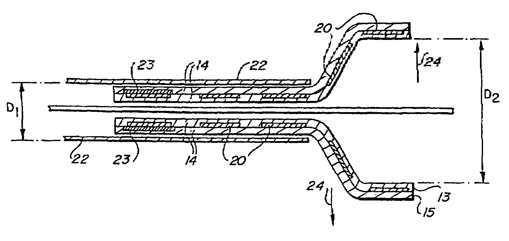
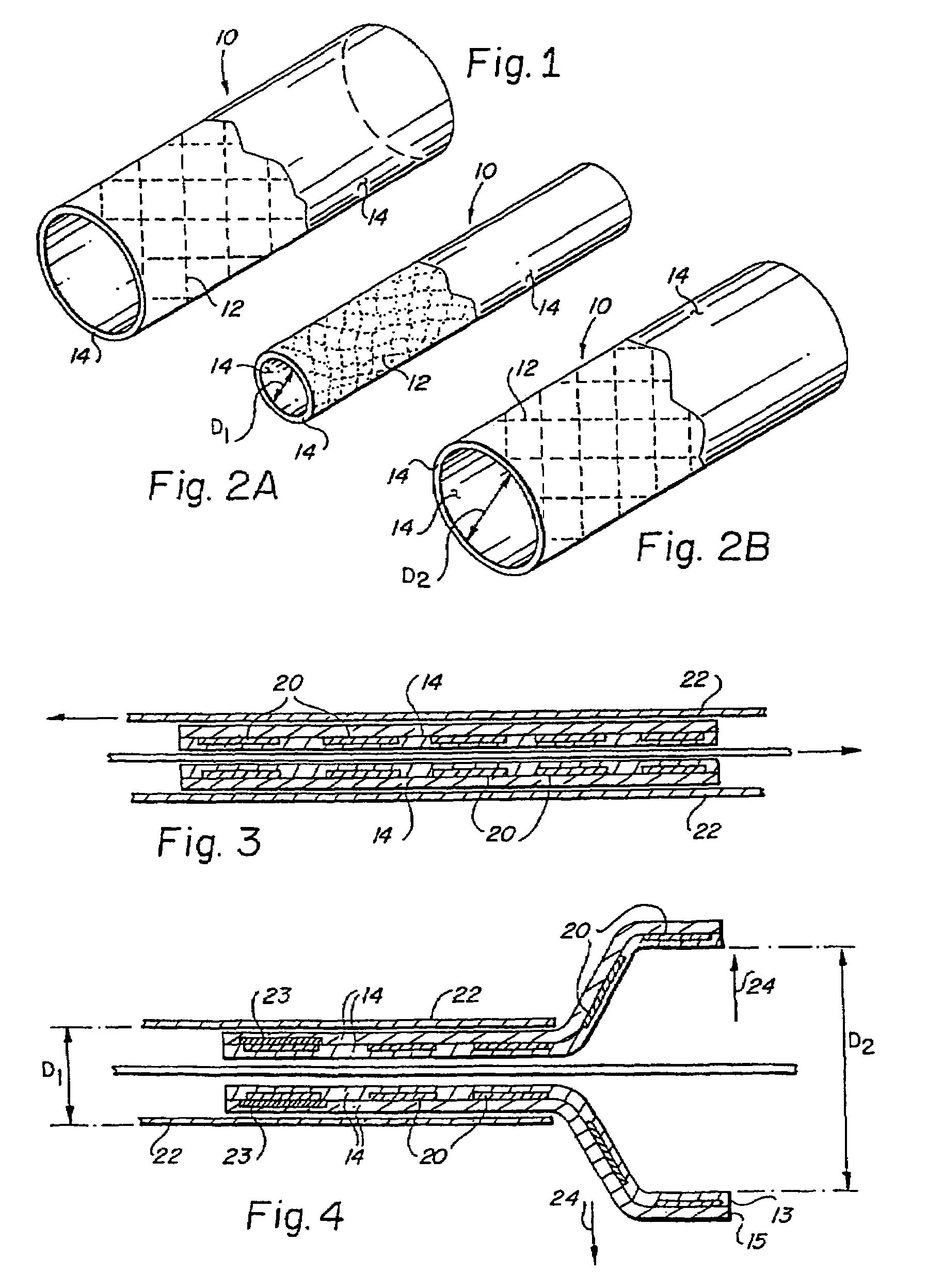
[0059]In accordance with a first preferred embodiment, illustrated in FIGS. 2A and 2B, there is provided a balloon expandable encapsulated shape memory alloy intraluminal stent 10. The balloon expandable encapsulated shape memory alloy intraluminal stent 10 consists generally of an endoluminal stent 12 fabricated of a shape memory alloy, preferably one having an As value at a physiologically acceptable temperature compatible with tissue conservation, such as equiatomic nickel-titanium alloys known as Nitinol. The endoluminal stent 12 is at least partially encapsulated in a substantially monolithic ePTFE covering 14 while the endoluminal stent 12 is in a relatively smaller diametric dimension D1. The substantially monolithic ePTFE covering 14 is a continuous integral tubular structure, is free of seams and covers at least part of both the luminal and abluminal surfaces about an entire circumferential section of the endoluminal stent 12 along at least a portion of the longitudinal axi...
example 1
Balloon Assisted Thermally Deployed Stent
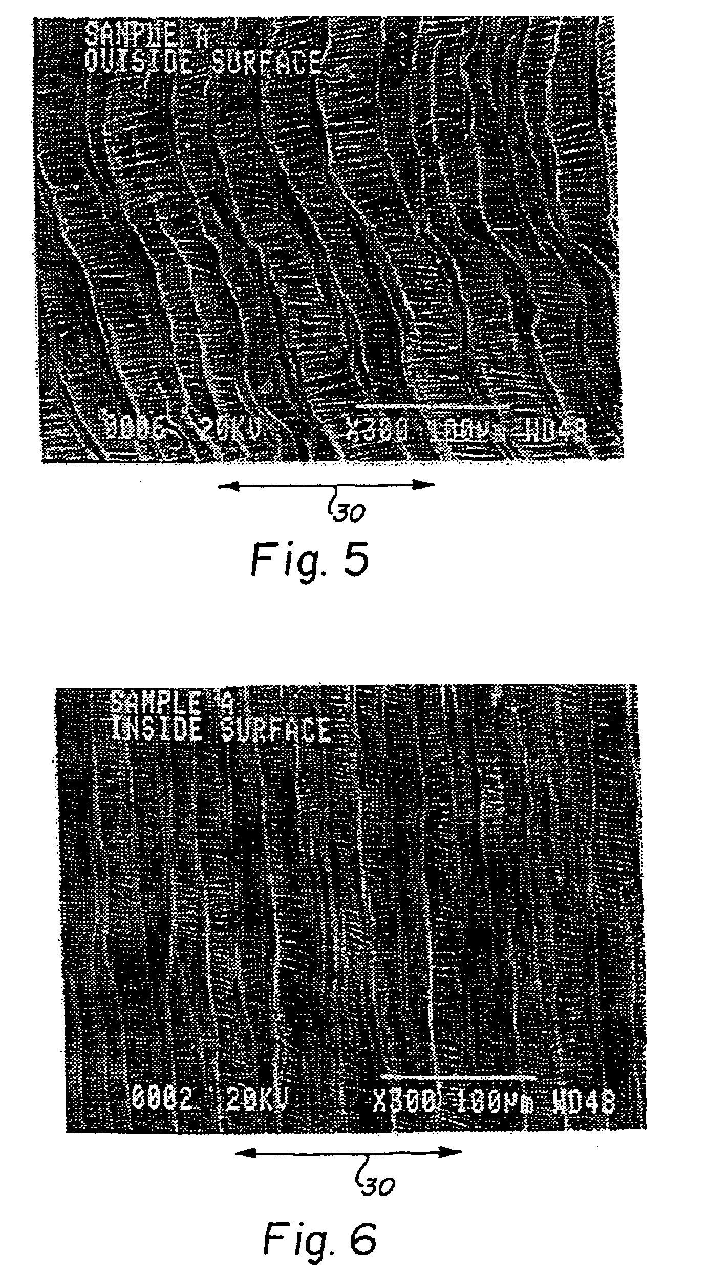
[0061]A balloon assisted encapsulated shape memory alloy stent was constructed by longitudinally slitting about 5 cm of a 60 cm length of a first seamless unsintered expanded PTFE tube having an inner diameter of 3.0 mm. The slit ends were gripped into a fixture allowing the tube to hang vertically. At the opposite end of the tube, a length of wire was attached to assist in threading the tubing through the inner diameter of the stent. The thickness of the ePTFE layer was measured to be about 0.35 mm using a snap gauge. The ePTFE tube exhibited a node-fibril microstructure in which the fibrils were oriented parallel to the longitudinal axis of the tube throughout the wall thickness of the ePTFE tube.
[0062]A 10×40 mm shape memory endoluminal stent was placed in a cold, dry environment at approximately −40° C. and compressed about a mandrel having an outer diameter of 4.5 mm by mechanically deforming the stent to circumferentially conform to the...
example 2
Thin Wall Thermally Deployed Stent
[0067]The radially expanded encapsulated stents obtained from Example 1 were placed over a 10 mm diameter stainless steel mandrel, and spiral wrapped using ½ inch ePTFE tape as described above.
[0068]The wrapped assembly was placed again into a radiant heat furnace, which had been preheated to 337° C. set point. The assembly remained in the furnace for about 10 minutes and was removed. The heated assembly was allowed to cool for a period of time sufficient to permit manual handling of the assembly. After air cooling, the ends of the mandrel was engaged in two rings and the TFE helical wrap was unwound from the encapsulated stent samples and discarded. The encapsulated stents were concentrically rotated about the axis of the mandrel to release adhesion between the luminal ePTFE surface of the encapsulated stent and the mandrel.
[0069]The encapsulated stent was next cooled to about −20° C. in a cold dry environment and allowed to equilibrate for 30 minu...
PUM
| Property | Measurement | Unit |
|---|---|---|
| pressures | aaaaa | aaaaa |
| pressures | aaaaa | aaaaa |
| inner diameter | aaaaa | aaaaa |
Abstract
Description
Claims
Application Information