Optical fiber coupler with low loss and high coupling coefficient and method of fabrication thereof

a technology of optical fiber couplers and coupling coefficients, applied in the field of couplers, can solve the problems of increasing insertion losses, reducing the coupling coefficient at each interface, and significant challenges in interfacing optical waveguide devices. achieve the effect of low loss and high coupling coefficient interfa

Active Publication Date: 2007-12-11
CHIRAL PHOTONICS
View PDF7 Cites 36 Cited by
  • Summary
  • Abstract
  • Description
  • Claims
  • Application Information

AI Technical Summary

Benefits of technology

[0021]The present invention is directed to a novel optical fiber coupler capable of providing a low loss, high coupling coefficient interface between conventional optical fibers and optical waveguide devices, even when the core diameters and numerical apertures differ. The novel coupler may be configured as a stand-alone device, or it may be integrated into an optical waveguide device.
[0022]The novel coupler includes a core, a cladding, a first end for interfacing with an optical fiber and a second end for interfacing with an optical waveguide device. The advantageous properties of the novel coupler are achieved as follows. Utilizing a pre-configured preform having a core and cladding, the sizes of the preform's core and cladding are gradually reduced from the first end to the second end, in accordance with a predetermined reduction profile. Various parameters, such as refractive indices, sizes of the core and cladding, and the reduction profile are selected to produce a low numerical aperture at the first end of the resulting coupler, and a high numerical aperture at the second end, while advantageously minimizing insertion loss and maximizing the coupling coefficient at each end.

Problems solved by technology

However, there are significant challenges in interfacing optical waveguide devices, including chiral optical fiber devices, with conventional low index contrast optical fibers.
Failure to properly address these obstacles results in increased insertion losses and a decreased coupling coefficient at each interface.
While attempts have been made to address the difficulties of interfacing between different optical fibers, as well as between optical fibers and signal sources, the proposed solutions do not address the challenge of mismatched apertures.
As a result, the connected optical fiber becomes undesirably multi-mode.
However, the approach proposed in the Newhouse patent increases the waveguide diameter of the connector.
As a result, the connector becomes multi-mode, and therefore loses the capability of maintaining a single, or a predetermined small number of modes which may be a key requirement in interfacing optical waveguide devices (e.g., planar waveguides, or chiral optical fiber devices) with conventional low-index-contrast optical fibers.
Furthermore, the connector disclosed in the Newhouse patent does not provide a solution for the challenge of mismatched apertures of optical waveguide devices and conventional optical fibers.

Method used


Image

  • Optical fiber coupler with low loss and high coupling coefficient and method of fabrication thereof
  • Optical fiber coupler with low loss and high coupling coefficient and method of fabrication thereof
  • Optical fiber coupler with low loss and high coupling coefficient and method of fabrication thereof

Examples


first embodiment

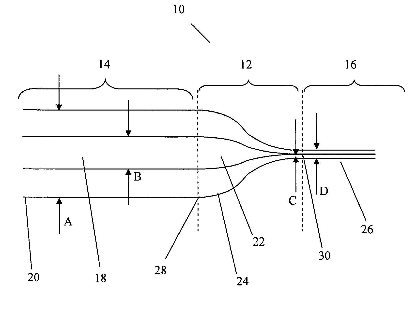
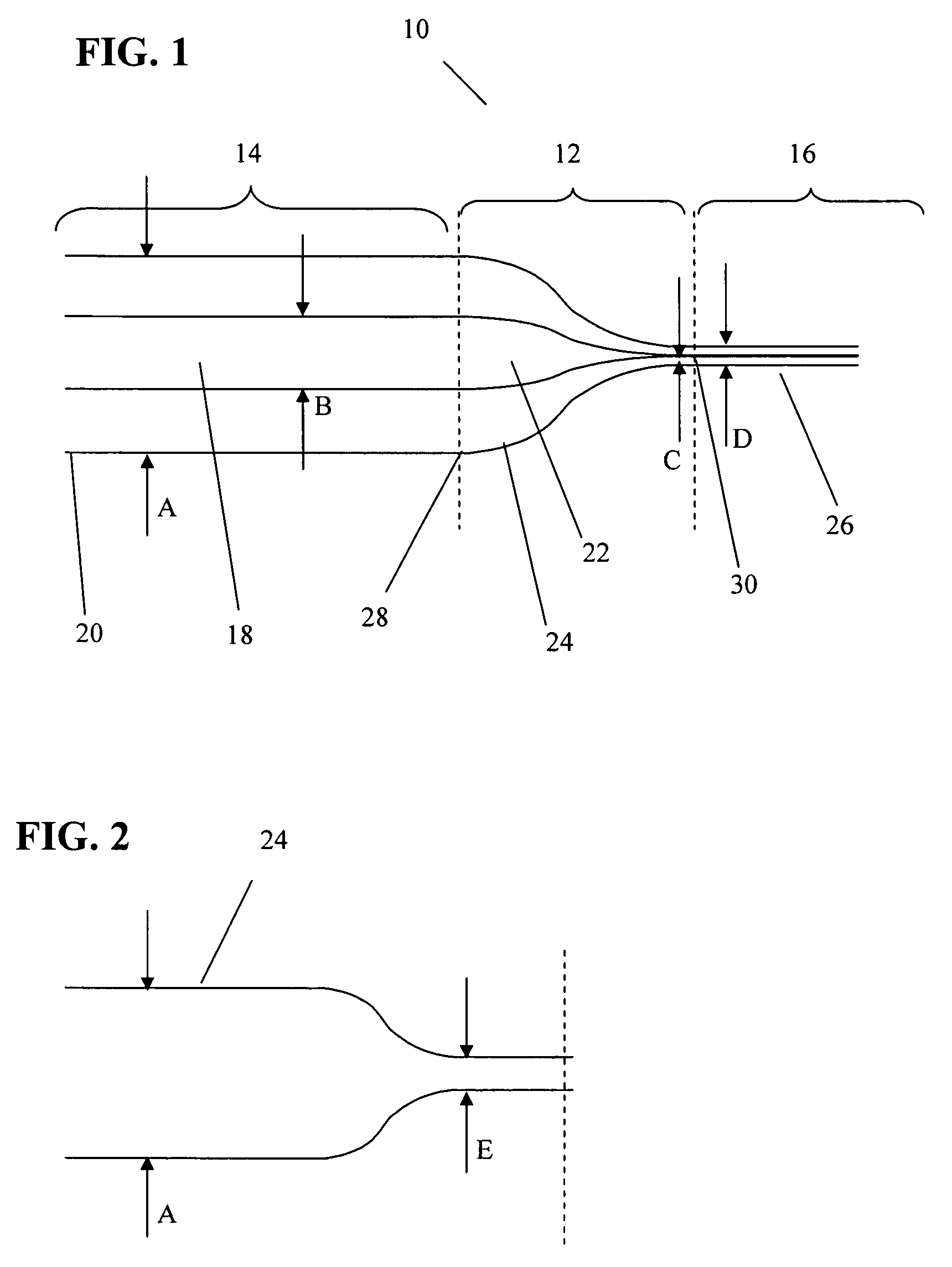
[0030]Referring now to FIG. 1, an inventive optical fiber coupler 12, is shown as part of an interface assembly 10. The coupler 12 serves as an interface between an optical fiber 14 (having an optical fiber core 18 and a cladding 20), and an optical waveguide device 16. Before describing the novel coupler 12 in greater detail, it would be helpful to discuss the optical fiber 14, and the optical waveguide device 16 in greater detail.

[0031]The optical fiber 14 may be a conventional low-index-contrast optical fiber with the core 18 and the cladding 20 (as shown in FIGS. 7A and 7B). As shown in FIG. 1, the optical fiber core 18 has a size B, while the optical fiber cladding 20 has a size A. An additional parameter of the optical fiber 14, is shown in FIG. 7B, as an angle θ, defining a “cone” within which light leaves the fiber core 18. Accordingly, the numerical aperture of the fiber 14 may be expressed as a sin(θ).

[0032]Alternately, the optical fiber 14, may be a polarization maintaini...

second embodiment

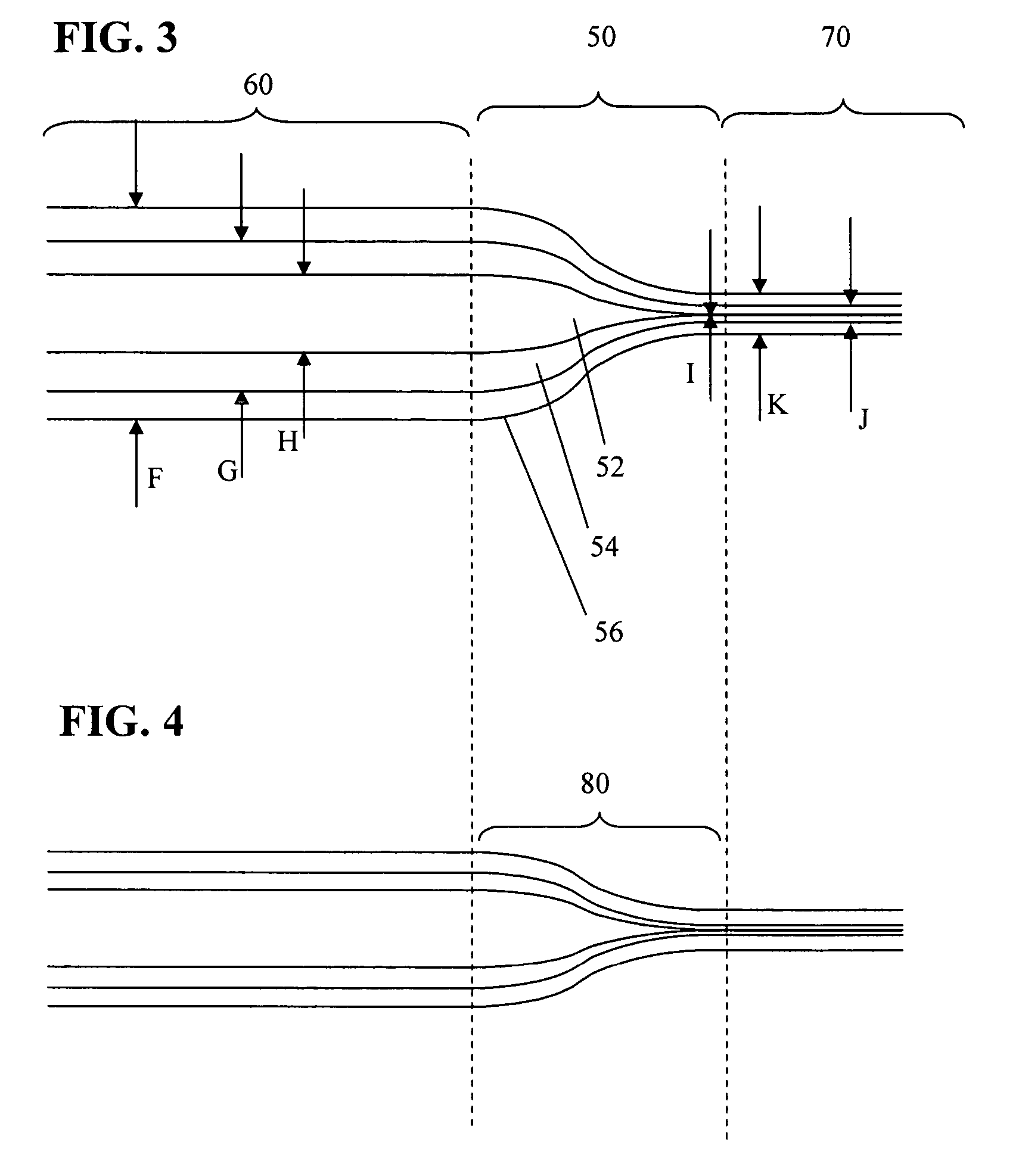
[0041]Referring now to FIG. 3, the coupler of the present invention is shown as a coupler 50, serving as an interface between an optical fiber 60, and an optical waveguide device 70. The optical fiber 60, and the optical waveguide device 70 are substantially similar to the fiber 14 and optical waveguide device 16 of FIG. 1, except that the medium surrounding these components is an additional cladding applied to each respective component 60, 70.

[0042]Similarly, the coupler 50, is equivalent to the coupler 12 of FIG. 1, except that the medium surrounding a core 52 and a cladding 54 thereof, is configured as a second cladding 56 (with the refractive index nm) surrounding the cladding 54. As the reduction profile is applied, the core 52 is reduced from size H to size I, the cladding 54 is reduced from size G to size J, while the second cladding 56 is reduced from size F to size K. This arrangement ensures that the second cladding 56 isolates and protects the reduced size cladding 54 fro...


PUM

PropertyMeasurementUnit
refractive indexaaaaaaaaaa
cladding sizeaaaaaaaaaa
refractive indicesaaaaaaaaaa

Abstract

An optical fiber coupler capable of providing a low loss, high coupling coefficient interface between conventional optical fibers and optical waveguide devices is provided. The novel coupler, which may be polarization maintaining, if a polarization maintaining preform is used in its fabrication includes a core, a cladding, a first end for interfacing with an optical fiber and a second end for interfacing with an optical waveguide device. The sizes of the core and cladding are gradually reduced from the first end to the second end in accordance with a predetermined reduction profile. Various parameters, such as refractive indices and sizes of the core and cladding and the reduction profile are selected to produce a low numerical aperture at the first end and a high numerical aperture at the second end, while advantageously minimizing insertion loss and maximizing the coupling coefficient at each end. In another embodiment, the novel coupler includes a secondary cladding which is also reduced between the first and second ends to improve the strength of the coupler structure at the second end. In yet another embodiment, one or two novel couplers are formed along with a chiral fiber based optical waveguide device as a single continuous element. The optical fiber preform used to fabricate the novel optical fiber coupler can be etched prior to fabrication to facilitate application of the reduction profile.

Description

CROSS REFERENCE TO RELATED APPLICATIONS[0001]The present patent application claims priority from the commonly assigned U.S. provisional patent application Ser. No. 60 / 530,517 entitled “Optical Fiber Coupler with Low Loss and High Coupling Coefficient and Method of Fabrication Thereof” filed Dec. 18, 2003.FIELD OF THE INVENTION[0002]The present invention relates generally to couplers, and more particularly to an optical fiber coupler capable of providing a low loss, high coupling coefficient interface between conventional optical fibers and optical waveguide devices.BACKGROUND OF THE INVENTION[0003]Optical waveguide devices are indispensable in various high technology industrial applications, and especially in telecommunications. In recent years, these devices, including planar waveguides, and two or three dimensional photonic crystals are being used increasingly in conjunction with conventional optical fibers. In particular, optical waveguide devices based on chiral optical fibers a...

Claims


Application Information

Patent Timeline
Patent Type & Authority Patents(United States)
IPC IPC(8): G02B6/26G02B6/42C03B37/012G02B6/024G02B6/28
CPCC03B37/01245G02B6/2843G02B6/024
Inventor KOPP, VICTOR IL'ICHTCHOURIKOV, VICTORSINGER, JONATHANNEUGROSCHL, DANIEL
Owner CHIRAL PHOTONICS
Why Eureka
Try Eureka