Electric gear motor drive for switching valve

a technology of electric gear motor and switching valve, which is applied in the direction of valve operating means/release devices, furnaces, lighting and heating apparatus, etc., can solve the problems of valve wear, disturbance and fluctuation of pressure and/or flow in the system, and reduce the efficiency of the apparatus, so as to reduce the volume, prevent the effect of process gas leakage, and eliminate the effect of ducting

Active Publication Date: 2007-12-18
DURR SYST INC
View PDF21 Cites 15 Cited by
  • Summary
  • Abstract
  • Description
  • Claims
  • Application Information

AI Technical Summary

Benefits of technology

[0010]The problems of the prior art have been overcome by the present invention, which provides an electric drive for a switching valve, the switching valve having such a drive, and a regenerative thermal oxidizer including the switching valve and drive system. The electric drive system allows for the starting and stopping of the rotation of a rotary valve with accurate positioning. The stopping of the valve includes dissipation of the kinetic energy of the valve by electric means. The valve is allowed to move vertically and oscillating rotary motion is possible.
[0012]In a preferred embodiment, the valve with which the drive system is used has a seal plate that defines two chambers, each chamber being a flow port that leads to one of two regenerative beds of the oxidizer. The valve also includes a switching flow distributor which provides alternate channeling of the inlet or outlet process gas to each half of the seal plate. The valve operates between two modes: a stationary mode and a valve movement mode. In the stationary mode, a tight gas seal is used to minimize or prevent process gas leakage. The gas seal also seals during valve movement. The valve is a compact design, thereby eliminating ducting typically required in conventional designs. This provides less volume for the process gas to occupy during cycling, which leads to less dirty process gas left untreated during cycling. Associated baffling minimizes or eliminates untreated process gas leakage across the valve during switch-over. The use of a single valve, rather than the two or four conventionally used, significantly reduces the area that requires sealing. The geometry of the switching flow distributor reduces the distance and number of turns the process gas goes through since the flow distributor can be located close to the heat exchange beds. This reduces the volume of trapped, untreated gas during valve switching. Since the process gas passes through the same valve ports in the inlet cycle as in the outlet cycle, gas distribution to the heat exchange beds is improved.
[0013]Valve switching with minimal pressure fluctuations, excellent sealing, and minimal or no bypass during switching is achieved. In view of the reduction or elimination of bypass during switching, the conventional entrapment chambers used to store the volume of unprocessed gas in the system during switching can be eliminated, thereby saving substantial costs.

Problems solved by technology

Any leakage of untreated process gas through the valve system will decrease the efficiency of the apparatus.
In addition, disturbances and fluctuations in the pressure and / or flow in the system can be caused during valve switch-over and are undesirable.
Valve wear is also problematic, especially in view of the high frequency of valve switching in regenerative thermal oxidizer applications.
The rack and pinion pneumatically powered drive system has a number of limitations.
However, the conditions acting on the rotary switch valve will vary and result in varying force on the valve sealing surface.
In some cases, it may not be able to rotate the valve.
In other cases, it may rotate the valve too quickly and overcome the means to stop the valve.
A second limitation of the pneumatically actuated drive system is the minimal braking capacity of the pneumatic cylinder.
These devices increase the cost and reduce reliability of the drive.
A third limitation of the pneumatically actuated drive is that use in cold environments requires an extremely dry air supply to prevent ice blockage of the air line.
This requires the addition of an expensive air drying device.
However, failure of the valve braking device or rotating the valve too quickly and exceeding the capacity of the braking device may allow the drive and / or valve to become damaged by impact with the stops.

Method used


Image

  • Electric gear motor drive for switching valve
  • Electric gear motor drive for switching valve
  • Electric gear motor drive for switching valve

Examples


Embodiment Construction

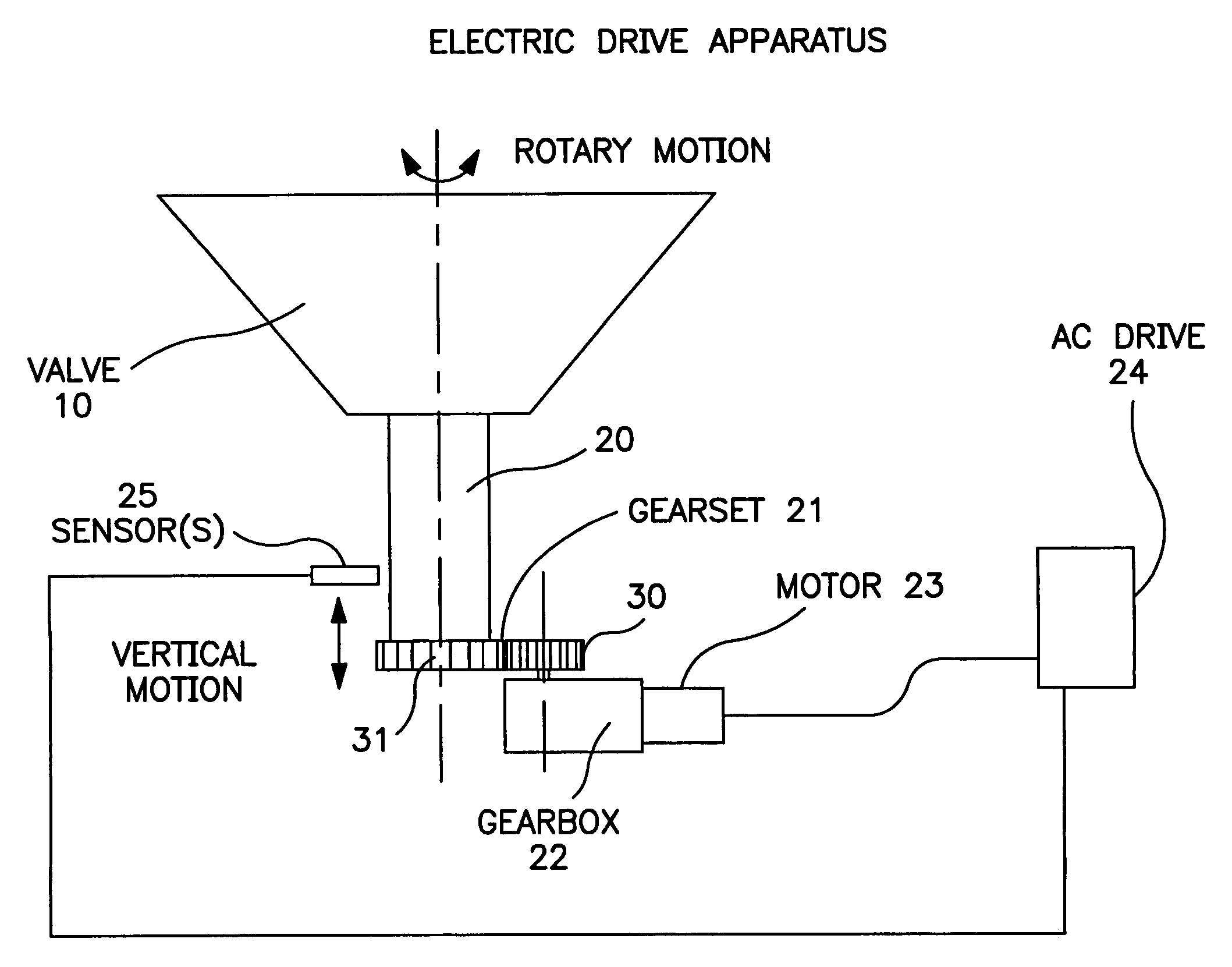
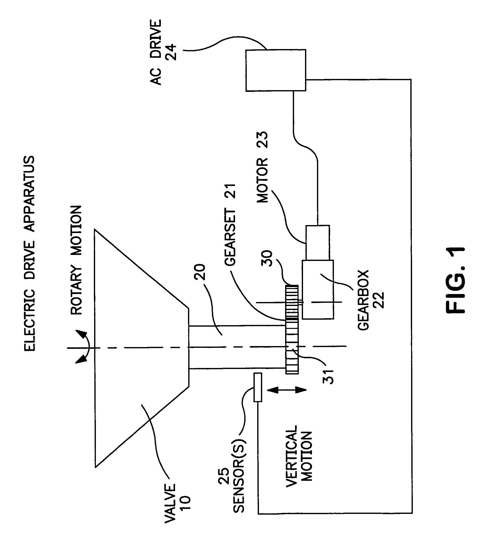
[0021]Turning first to FIGS. 1 and 2, there is shown schematically the electric gear motor drive system in accordance with one embodiment of the present invention, coupled to a rotary valve 10. The valve 10 includes a shaft 20 connected to a gear set 21. The gear set 21 is driven by gears housed in gear box 22, which are driven by motor 23 powered by an AC drive 24 as shown. In the embodiment shown, the gear box 22 is supported by a gearbox mounting plate 7 (FIG. 3) that is in turn supported by a pair of spaced base frame mounting beams 5. This structure is capable of withstanding the torque that occurs during operation of the system. Gear set 21 is made up of gears 30 and 31. Gear 30 mates to gear 31 mounted to the valve, such as on shaft 20. Gear 30 is driven by the gears in the gear box 22, which in turn are driven by motor 23. Preferably the gears 30, 31 are spur gears to allow the assembly to accommodate vertical motion of the valve 10. Vertical motion is typically done using a...


PUM


Abstract

Electric drive for a switching valve, the switching valve having such a drive, and a regenerative thermal oxidizer including the switching valve and drive system. The electric drive system allows for the starting and stopping of the rotation of a rotary valve with accurate positioning. The stopping of the valve includes dissipation of the kinetic energy of the valve by electric means. The valve is allowed to move vertically and oscillating rotary motion is possible. The drive system preferably includes a gear, gearbox, variable speed drive and at least one positioning sensor. Valve acceleration and deceleration can be carried out in a controlled fashion and with repeatability, so that the final end position of the valve is consistent. The accommodation of vertical movement of the valve is also within the scope of the present invention.

Description

BACKGROUND OF THE INVENTION[0001]Regenerative thermal oxidizers are conventionally used for destroying volatile organic compounds (VOCs) in high flow, low concentration emissions from industrial and power plants. Such oxidizers typically require high oxidation temperatures in order to achieve high VOC destruction. To achieve high heat recovery efficiency, the “dirty” process gas which is to be treated is preheated before oxidation. A heat exchanger column is typically provided to preheat these gases. The column is usually packed with a heat exchange material having good thermal and mechanical stability and sufficient thermal mass. In operation, the process gas is fed through a previously heated heat exchanger column, which, in turn, heats the process gas to a temperature approaching or attaining its VOC oxidation temperature. This pre-heated process gas is then directed into a combustion zone where any incomplete VOC oxidation is usually completed. The treated now “clean” gas is the...

Claims


Application Information

Patent Timeline
Patent Type & Authority Patents(United States)
IPC IPC(8): F16K31/04
CPCF16K31/046Y02E20/12Y10T137/8242Y10T137/5689F16K31/041F16K31/535
Inventor BRIA, MICHAEL P.GLENN, GEORGE D.SCHNEIDER, RANDALL M.
Owner DURR SYST INC
Why Eureka
Try Eureka