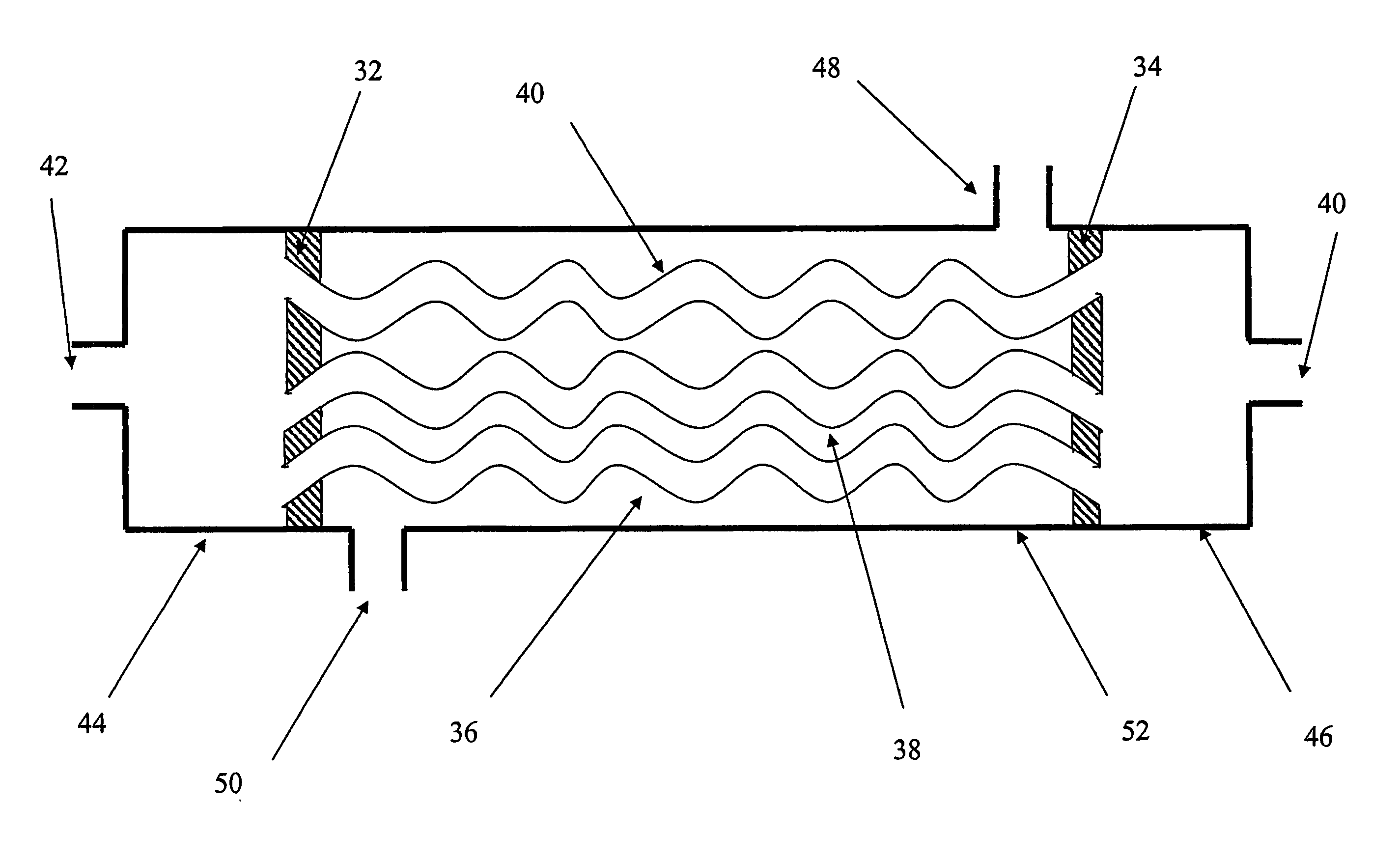
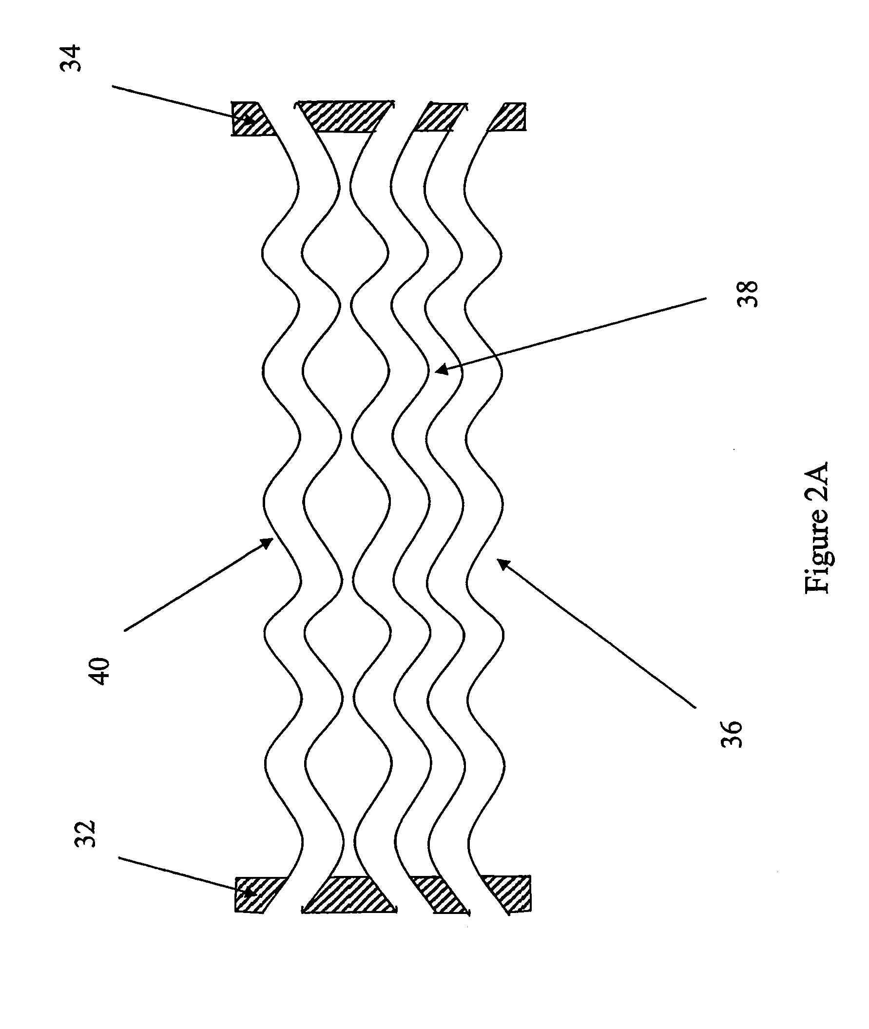
Exchange apparatus

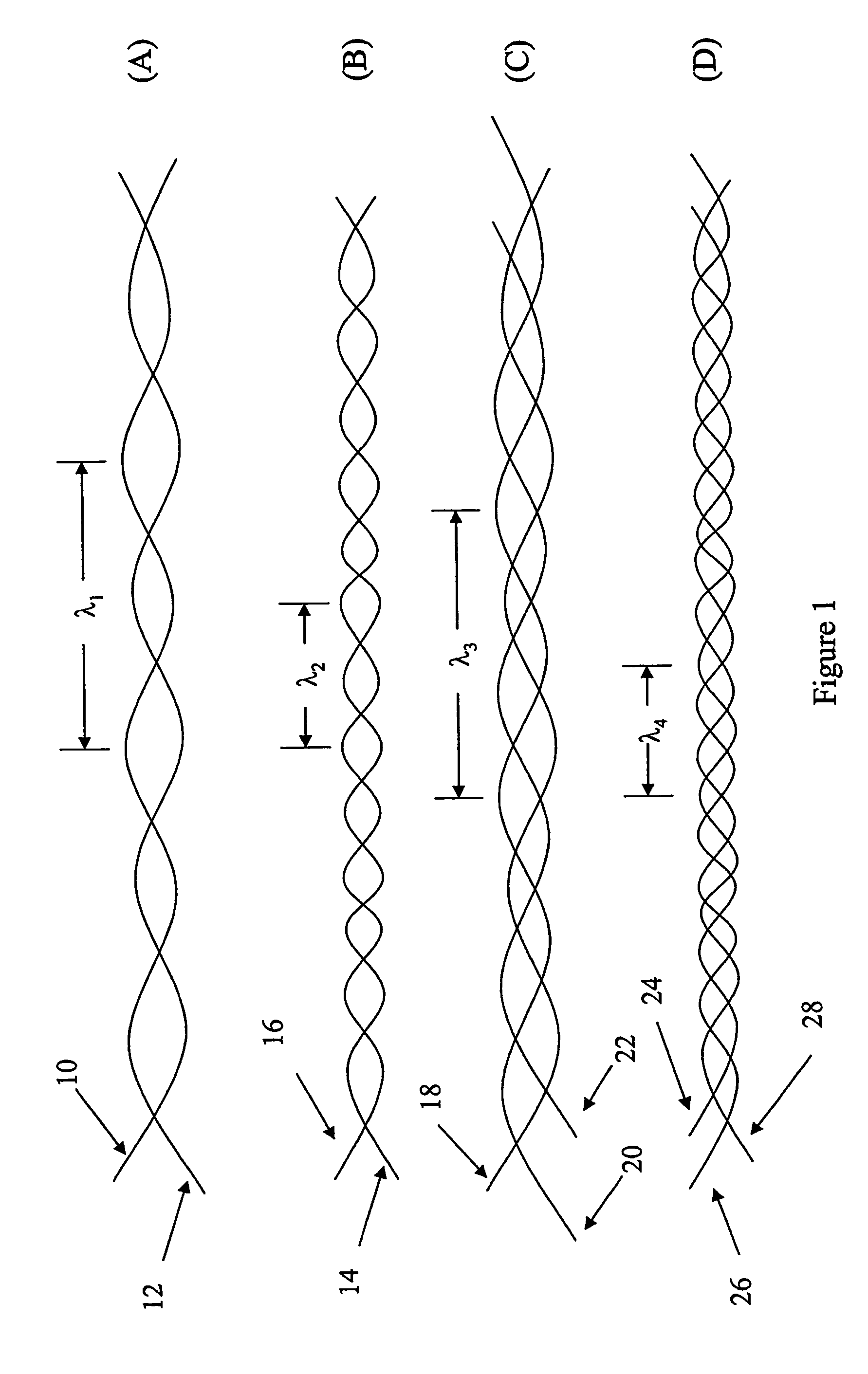
a technology of membrane exchange and hollow tube, which is applied in the direction of lighting and heating apparatus, membranes, separation processes, etc., can solve the problems of large volume of chemical or exchange fluid, large device occupying valuable space, and inability to exchange fluid, etc., to achieve enhanced fluid flow distribution and high packing density of hollow tubes or cords

Active Publication Date: 2007-12-18
ENTEGRIS INC
View PDF33 Cites 44 Cited by
  • Summary
  • Abstract
  • Description
  • Claims
  • Application Information

AI Technical Summary

Benefits of technology

[0020]In one embodiment the hollow tubes in the apparatus are braided, plaited, or twisted together to create a cord of the tubes or fibers prior to fusion bonding into the thermoplastic resin to form a unified terminal block. Such cords provide enhanced flow distribution of fluid through the apparatus without the need for baffling. A high packing density of hollow tubes or cords is achieved with this invention.

Problems solved by technology

However, polymeric heat exchange devices are usually large because a high heat transfer surface area is required to effect a given temperature change due to the low thermal conductivity of the polymers used in the device.
Such devices take up valuable space, requires large holdup volumes of chemicals or exchange fluid, and are costly to make.
Such devices also require o-ring seals which are prone to failure and are also a source of ionic and particulate contamination.
Quartz is susceptible to breakage and exposed resistively heated surfaces pose fire and explosion hazards especially for organic liquids and liquids which evolve flammable gases.
Baffling of perfluronated tubes is not practical using this technique.
It is cumbersome, and expensive to manufacture exchange contactors using this technique.
Such a method does not contemplate the use of thermoplastics nor does it address the need for the substantially higher surface area required for low thermally conductive thermoplastic materials.
Such a method produces an irregular pattern of entrances to the hollows of the tubes effecting non-uniform flow distribution to the tubes.
Such a device requires mechanical fixtures to hold the tubes in place and as such requires a large volume of space.
The authors observe that hand built modules have more uniform fiber spacing but that the cost of such modules do not justify their higher manufacturing cost.
Such a device method requires expensive and complicated weaving equipment to fix the fibers in a preferred relationship in the tube mats.
Currently it is impractical to use thermoplastic heat exchangers for large heat loads, shell side liquid flow, or efficient shell side cross flow filtration because of the high expense and large size of devices needed.
Metal heat exchangers are unacceptable for use in semiconductor manufacturing because of the corrosive nature of the chemicals and also because of the need to eliminate metallic and particulate impurities from process liquids.

Method used


Image

  • Exchange apparatus
  • Exchange apparatus
  • Exchange apparatus

Examples


example 1

[0057]A prototype heat exchanger having a housing with a 1 inch inside diameter PFA tube was prepared by Procedure 1 except that the tubes were not twisted or annealed. The device contained 150 tubes of straight MFA tube measuring 15 inches in length.

[0058]The prototypes was tested under the following conditions. Hot water at a temperature of 63° C. was fed into the tube side of the device at a flow rate of approximately 1750 ml / min. Cold water at a temperature of 19° C. was fed into the shell side of the device at a flow rate of approximately 1070 ml / min. The hot and cold water paths flowed countercurrent to one another. The inlet and outlet temperatures and the flow rates were recorded every five minutes for the tube and shell side fluid streams for one hour. The results from this experiment are detailed in Table 1 shown in FIG. 6. Under these conditions the cold water was heated from 18.9° C. to 38.8° C. and a total of 1486 watts of energy was exchanged between the two fluids.

example 2

[0059]A prototype heat exchange apparatus having a housing with a 1 inch inside diameter PFA tube was prepared by Procedure 1 except that it contained about 150 hollow MFA tubes twisted together with about 12 twists per foot. The twisted cords were annealed on a metal rack to yield approximately 75 cords measuring about 15 inches in length.

[0060]The prototype was tested under the following conditions. Hot water at a temperature of 55° C. was fed into the tube side of the device at a flow rate of approximately 1650 ml / min. Cold water at a temperature of 19° C. was fed into the shell side of the device at a flow rate of approximately 1070 ml / min. The hot and cold water paths flowed countercurrent to one another. The inlet and outlet temperatures and the flow rates were recorded every five minutes for the tube and shell side fluid streams for one hour. The results from this experiment are detailed in Table 1 in FIG. 6. Under these conditions the cold water was heated to from 18.9° C. t...

example 3

[0061]This prospective example shows how a wafer processing tool including the exchange apparatus of this invention can be used to heat liquids used for cleaning semiconductor wafers.

[0062]An exchange apparatus having about 650 twisted hollow MFA tubes, 325 pairs, can be thermally annealed and fusion bonded in a 2 inch inside diameter PFA tube using the methods of Procedure 1. The length of the device can be about 18 inches and has a liquid volume of about 300 millliliters. The device is part of a wafer processing tool and is connected at its inlet fluid connection to an in-line to a source of aqueous 10% hydrochloric acid containing about 1 percent by volume hydrogen peroxide. The outlet of the exchange device is connected to a valve, optional stop suck back valve, and nozzle for dispensing the aqueous acid solution onto a substrate to be cleaned. One of the fluid inlet connections on the shell side of the exchange device is connected in-line to a source of hot water. Hot deionized...


PUM

PropertyMeasurementUnit
thicknessaaaaaaaaaa
diameteraaaaaaaaaa
diameteraaaaaaaaaa

Abstract

An exchange apparatus comprised of hollow thermoplastic tubes infusion bonded into a thermoplastic material is disclosed. In a preferred embodiment the hollow tubes are shaped by plaiting the tubes into cords and then thermally annealing the cords to set the crests and bends of the plait. The cords provide improved flow distribution of fluid about the hollow tube tubes in the exchange apparatus. The exchange apparatus is chemically inert and is useful for cross flow filtration, as well as heat and mass transfer in harsh chemical environments.

Description

RELATED APPLICATIONS[0001]This application claims the benefit of provisional application Ser. No. 60 / 326,234 filed Oct. 1, 2001 entitled Fluid Exchange Device. This application is related to co-pending application filed concurrently herewith as U.S. Ser. No. 60 / 326,357, filed Oct. 1, 2001 under Applicants' reference number 200100293 (formerly MYKP-621).FIELD OF INVENTION[0002]This invention relates to a hollow tube or hollow fiber membrane exchange apparatus useful for heat transfer, particle filtration, and mass transfer applications. The apparatus comprises a housing containing fusion bonded hollow tubes that have been previously plaited and thermally annealed to set the plait. The apparatus has a high packing density of hollow tubes with enhanced fluid flow distribution provided by the plaited hollow tubes. The apparatus provides high contacting area in a small volume without the need for baffles. The device is made from chemically inert thermoplastic materials and has the abilit...

Claims


Application Information

Patent Timeline
Patent Type & Authority Patents(United States)
IPC IPC(8): F28F9/02B21D53/02F28D7/02B01D53/22B01D61/02B01D61/14B01D63/00B01D63/02B01D63/06B01D69/08B01D71/26B01D71/32B01D71/36B01D71/52C02F1/44F28D7/08F28D7/10F28D7/16F28D9/02F28F1/10F28F9/18F28F21/06
CPCB01D63/02B01D63/022B01D63/06B01D63/061B01D63/068B01D69/084F28D7/08F28D7/082F28F9/187F28F21/062B01D63/021Y10T29/49362Y10S165/905B01D2313/38Y10T29/49373Y10T29/4935B01D2313/221F28D7/02
Inventor DOH, CHA P.CHENG, KWOK-SHUNLAFORGE, ALICIA BRIGGS
Owner ENTEGRIS INC
Why Eureka
Try Eureka