Narrow pore size distribution cordierite filters with reduced pressure drop

a cordierite filter and pore size distribution technology, applied in the field of cordierite wallflow diesel particulate filters, can solve the problems of increasing resistance, increasing the pressure drop across the filter, and reducing the fuel efficiency of the vehicl

Inactive Publication Date: 2007-12-18
CORNING INC
View PDF24 Cites 22 Cited by
  • Summary
  • Abstract
  • Description
  • Claims
  • Application Information

AI Technical Summary

Benefits of technology

[0037]Therefore, the present invention is advantageous in providing a lower pressure drop cordierite diesel particulate filter relative to commercially available filters due to improved pore connectivity. The improved pore connectivity is a consequence of the narrow pore size distribution and high % porosity. The inventive filters are especially suitable for applications in which the filter is coated with a catalyst system, however may be used in uncatalyzed applications. The lower pressure drop will enable more efficient operation of the diesel engine and improved fuel economy. Despite having a high porosity, the inventive filters possess a high filtration efficiency since a low pressure drop can be achieved without requiring coarse porosity that would allow the passage of soot particles through the filter walls. The inventive filters also have excellent strength due to the absence of coarse pores, despite a high porosity.

Problems solved by technology

The presence of soot within the filter walls lowers the overall permeability of the wall, thereby increasing the resistance of gas flow through the wall and increasing the pressure drop across the filter.
Various strategies have been adopted to provide this energy, all of which reduce the fuel efficiency of the vehicle.
It has been observed, however, that the application of a catalyst system to a DPF causes an increase in the pressure drop across the clean and soot-loaded filter.
This change in pore microstructure reduces the permeability of the clean wall prior to soot loading, and also reduces the permeability of the soot-containing wall for any given mass of soot.
However, this combination of high porosity and large pore size causes lower filtration efficiency and lower mechanical strength, and does not yield an optimized filter.
Furthermore, non-uniform distribution of the catalyst can result from broad pore size distributions.

Method used


Image

  • Narrow pore size distribution cordierite filters with reduced pressure drop
  • Narrow pore size distribution cordierite filters with reduced pressure drop
  • Narrow pore size distribution cordierite filters with reduced pressure drop

Examples


examples

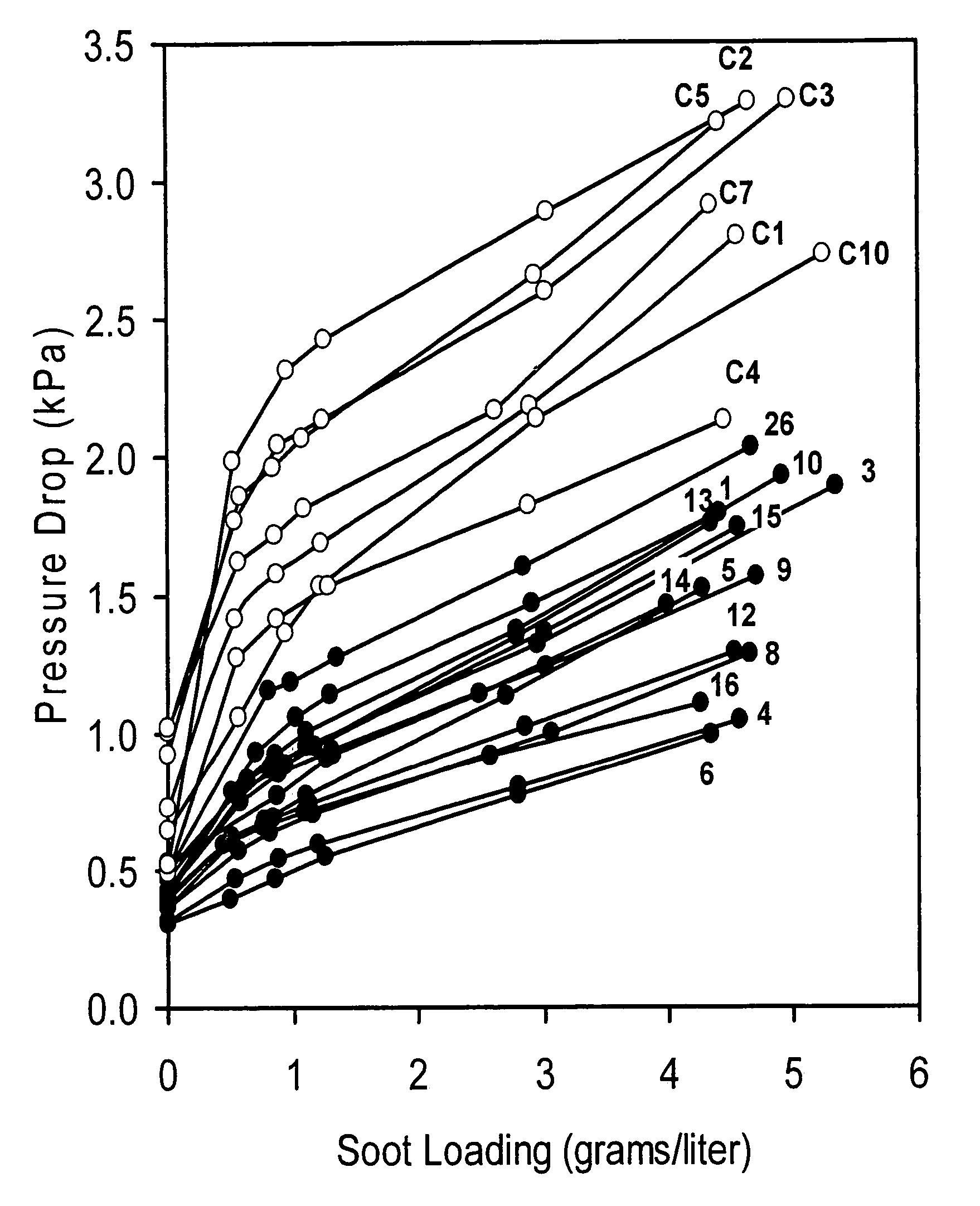
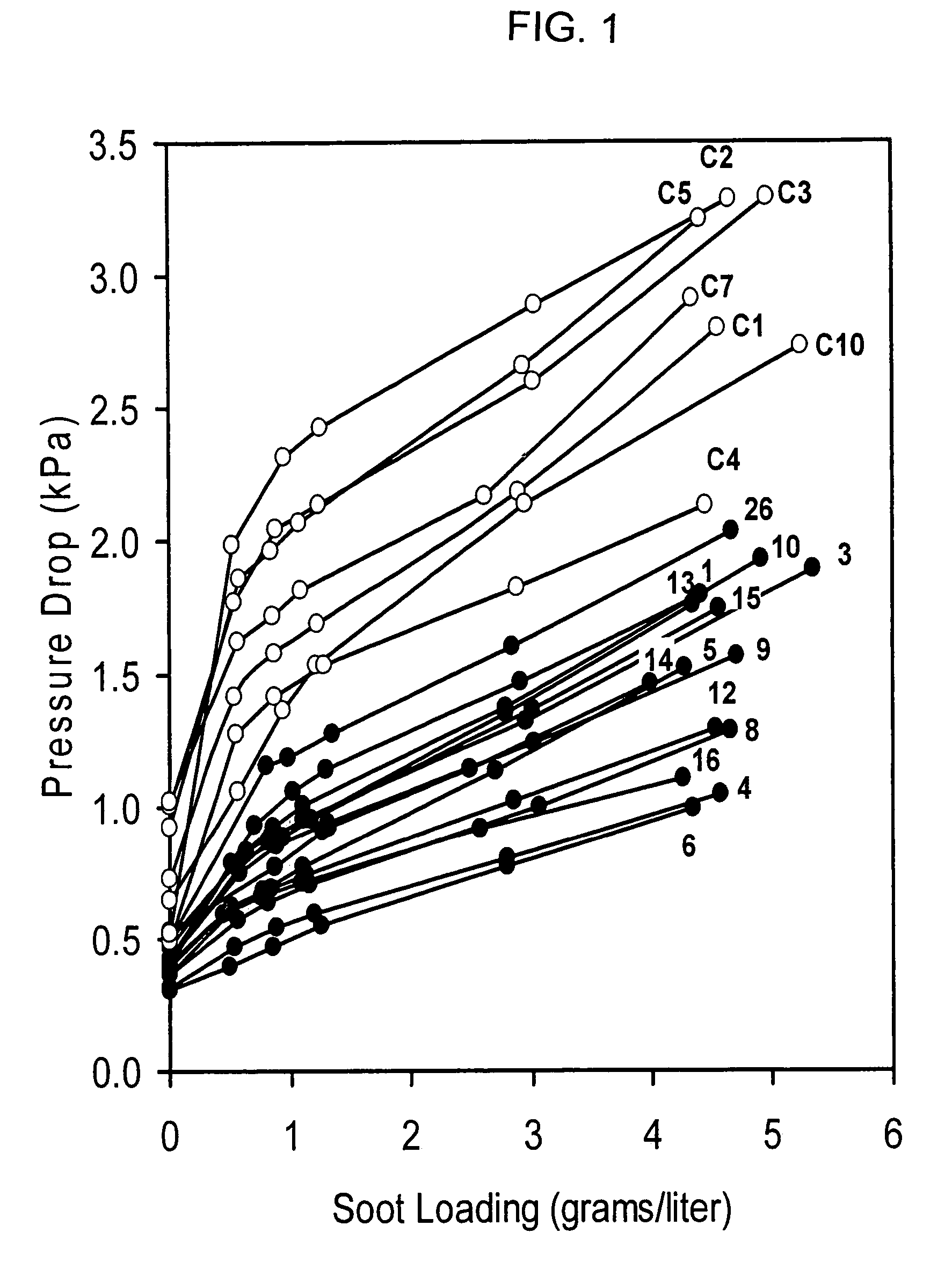
[0030]Inventive and comparative examples are prepared by mixing together selected raw materials from Table 1 in the proportions listed for the examples in Tables 2 to 8. 100 parts by weight of the dry ingredients (oxides plus pore formers) are mixed with about 4 to 6 parts by weight methyl cellulose and 0.5 to 1 part by weight sodium stearate. The contents are then plasticized with about 25 to 40 parts by weight deionized water, and are extruded into honeycomb having a nominal cell density of 200 cells / inch2 and a wall thickness of 0.012 inches to 0.020 inches. The honeycombs are dried and subsequently fired to a temperature of 1405° C. to 1415° C., held at that temperature for 11 to 25 hours, and then cooled to room temperature.

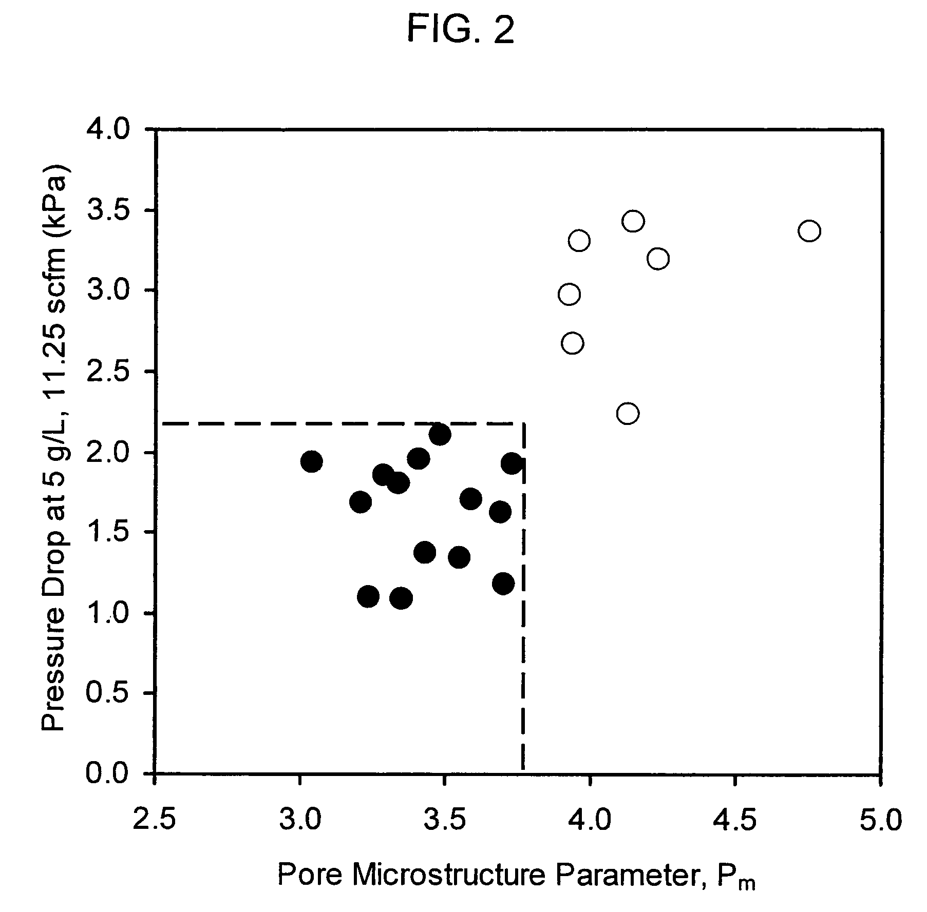
[0031]Properties of comparative (non-inventive) examples are provided in Tables 2 and 3 and properties of inventive examples are given in Tables 4 to 8 Pore volume, % porosity, and pore size distribution are measured by mercury porosimetry. Coefficient of th...


PUM

PropertyMeasurementUnit
pore diameteraaaaaaaaaa
porosityaaaaaaaaaa
pore diametersaaaaaaaaaa

Abstract

A diesel particulate filter having a honeycomb body composed of cordierite and exhibiting a CTE (25-800° C.) of less than 13×10−7 / ° C.; a median pore diameter, d50, of less than 25 μm; % porosity not less than 53%; and a narrow pore size distribution wherein a value of d50<sup2>−< / sup2>d10) / d50 is not greater than 0.6; and a value of d90 less than 40 μm wherein d10, and d90 are pore diameters at 10% and 90% of the pore size distribution on a volumetric basis, and d10<d50<d90. The particulate filter preferably exhibits a plugged, wall-flow honeycomb filter body composed of cordierite and having a plurality of parallel end-plugged cell channels traversing the body from a frontal inlet end to an outlet end thereof.

Description

RELATED INVENTIONS[0001]The present invention is a continuation of and claims priority to and the benefit of U.S. patent application Ser. No. 10 / 607,249 filed Jun. 25, 2003 and entitled “Cordierite Filters with Reduced Pressure Drop”, now issued as U.S. Pat. No. 7,179,316 on Feb. 20, 2007.BACKGROUND OF THE INVENTION[0002]The present invention relates to diesel particulate filters, and in particular to cordierite wall-flow diesel particulate filters having high filtration efficiency, high strength and low pressure drops for catalyzed and uncatalyzed applications.[0003]Porous, wall-flow ceramic filters have been utilized for the removal of carbonaceous soot particles from the exhaust stream of diesel engines since the early 1980s. A porous ceramic diesel particulate filter (DPF) ideally combines low CTE (for thermal shock resistance), low pressure drop (for engine efficiency and fuel economy), high filtration efficiency (for removal of most particles from the exhaust stream), high str...

Claims


Application Information

Patent Timeline
Patent Type & Authority Patents(United States)
IPC IPC(8): B01D46/00F01N3/022B01D39/06B01D39/20B01D46/24C04B35/195C04B38/00F01NF01N3/02
CPCC04B35/195C04B38/0006B01D46/2429C04B38/0054C04B38/0067C04B38/0074C04B38/0645C04B38/067C04B38/068B01D46/2425Y10S55/10B01D46/244B01D46/2444B01D46/2466B01D46/247B01D2046/2433B01D2046/2437B01D2046/2496C04B2111/00198C04B2111/00793C04B2111/0081C04B2111/2084C04B2111/32Y10S55/30B01D46/24492B01D46/24491B01D46/2498B01D46/2484B01D46/2482B01D46/24494B01D46/24493B01D46/2474
Inventor MERKEL, GREGORY A.TAO, TINGHONG
Owner CORNING INC
Why Eureka
Try Eureka