Switching system

a switching system and switching technology, applied in the field of digital information processing, can solve the problems of not enabling seamless connection and interoperability between disparate storage platforms and protocols, not well-adapted to communicate with one another, and san devices do not integrate well with existing ip-based management systems, so as to accelerate tcp processing and improve system stability

Active Publication Date: 2007-12-25
ORACLE INT CORP
View PDF22 Cites 216 Cited by
  • Summary
  • Abstract
  • Description
  • Claims
  • Application Information

AI Technical Summary

Benefits of technology

[0025]Still another aspect of the invention provides TCP/UDP acceleration, with IP stack bypass using a network processors (NP). The present invention simultaneously maintaining TCP state information in both the fast path and the slow path. Control messages are exchanged between the fast path and slow path processing engines to maintain state synchronization, and to hand off control from o

Problems solved by technology

Conventional systems, however, do not enable seamless connection and interoperability among disparate storage platforms and protocols.
Users are often require to deal with multiple suppliers of routers, switches, host bus adapters and other components, some of which are not well-adapted to communicate with one another.
Vendors and standards bodies continue to determine the protocols to be used to interface devices in SANs and NAS configurations; and SAN devices do not integrate well with existing IP-based management systems.
Still further, the storage devices (Disks, RAID Arrays, and the like), which are Fibre Channel attached to the SAN devices, typically do not support IP (and the SAN devices have limited IP support) and the storage devices cannot be discovered/managed by IP-based management systems.
Although TCP is useful, it requires substantial processing by the system CPU, thus limiting throughput and system performance.
However, this approa

Method used


Image

  • Switching system
  • Switching system
  • Switching system

Examples


examples

Set 2

2. UML Static Structure Diagram

[0720]FIG. 37 is a representation of the NCM, IXP and NAS server classes. For each, the top box is the name, the second box contains attributes of an instance of this class and the bottom box describes the methods each class must implement.

[0721]Attributes Description

[0722]Data local to an instance of the class that make it unique.

[0723]Methods Description

[0724]Those preceded with a + are public and usually invoked by receiving a message. The method is preceded by the name of the sender of the message surrounded by >. Calling out the sender in the description should help you to correlate the messaging scenarios described in this document to implemented methods in the classes. Those preceded by a − are private methods that may be invoked during processing of public methods. They help to organize and reuse functions performed by the class.

VIII. System Mediation Manager

[0725]The following discussion sets forth the functional specification and design ...


PUM


Abstract

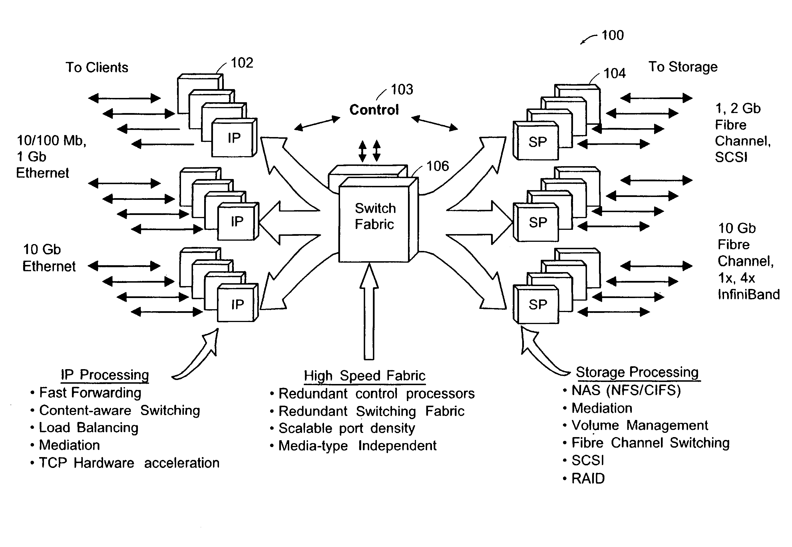
A system and method for provided a switch system (100) having a first configurable set of processor elements (102) to process storage resource connection requests (104), a second configurable set of processor elements capable of communications with the first configurable set of processor elements (102) to receive, from the first configurable set of processor elements, storage connection requests representative of client requests, and to route the requests to at least one of the storage elements (104), and a configurable switching fabric (106) interconnected between the first and second sets of processor elements (102), for receiving at least a first storage connection request (104) from one of the first set of processor elements (102), determining an appropriate one of the second set of processors for processing the storage connection request (104), automatically configuring the storage connection request in accordance with a protocol utilized by the selected one of the second set of processors, and forwarding the storage connection request to the selected one of the second set of processors for routing to at least one of the storage elements.

Description

INCORPORATION BY REFERENCE / PRIORITY CLAIM[0001]Commonly owned U.S. provisional application for patent Ser. No. 60 / 245,295 filed Nov. 2, 2000, incorporated by reference herein; and[0002]Commonly owned U.S. provisional application for patent Ser. No. 60 / 301,378 filed Jun. 27, 2001, incorporated by reference herein.[0003]Additional publications are incorporated by reference herein as set forth below.FIELD OF THE INVENTION[0004]The present invention relates to digital information processing, and particularly to methods, systems and protocols for managing storage in digital networks.BACKGROUND OF THE INVENTION[0005]The rapid growth of the Internet and other networked systems has accelerated the need for processing, transferring and managing data in and across networks.[0006]In order to meet these demands, enterprise storage architectures have been developed, which typically provide access to a physical storage pool through multiple independent SCSI channels interconnected with storage vi...

Claims


Application Information

Patent Timeline
IPC IPC(8): G06F15/173G06F12/00G06F3/06G06F15/16H04L12/56H04L29/08
CPCG06F11/2074H04L67/1097G06F3/0613G06F3/0635G06F3/067G06F11/2087H04L49/201H04L49/351H04L49/354H04L49/355H04L49/1523
Inventor CONSIDINE, JOHNHALL, HOWARDCOCHRANE, CHRISTOPHER
Owner ORACLE INT CORP
Why Eureka
Try Eureka