Fiber optic rotary coupling and devices

a technology of rotary coupling and fiber optic cables, applied in the field of optical systems, can solve the problems of increasing insertion loss, fiber optic cables can easily be damaged by small shear force, and considerable care in handling fiber optic cables, and achieves low loss and convenient fashion, reduce friction, and reduce the effect of loss and convenien

Active Publication Date: 2008-01-01
TELESCENT
View PDF3 Cites 198 Cited by
  • Summary
  • Abstract
  • Description
  • Claims
  • Application Information

AI Technical Summary

Benefits of technology

[0010]It is an object of the present invention to provide a fiber optic rotary unit comprised of one or more continuous lengths of optical fiber and to provide a retractable, coiled fiber optic cable assembly including the rotary unit therein. The retractable cable assembly protects excess lengths of fiber optic cable in a low loss and convenient fashion. This cable may be of the simplex, duplex, or ribbon cable type, for example. A central point on the cable is rigidly attached to the reel and this point rotates as the cable is retracted or extended to controllable lengths. The spool rotates about a central shaft, under the force of a power spring which transfers a torsion force adequate to wind the extended fiber optic cable onto the rotating reel. The reel incorporates a hub with notched segments on its periphery to engage a force balanced, spring loaded ratchet-pawl mechanism. This mechanism permits smooth cable extension throughout the entire range of fiber extension and securely locks the reel to maintain the fiber optic cable at the desired length.
[0011]The fiber optic cable is attached to the rotating reel and maintains optical and physical continuity as the same fiber enters the rotary interface. The rotary interface consists of a spiral spring-optical fiber combination which accommodates winding or unwinding of the optical fiber in a low loss fashion. The spring provides rigidity and reduced friction such that winding and unwinding of a substantial number of turns is accomplished without subjecting the fiber to excessive bends. The fiber optic cable exits the fixed end of the rotary interface which is attached to an enclosure.

Problems solved by technology

A unique characteristic of fiber-based transmission media is that considerable care must be taken in handling fiber optic cables because of the potential to damage the internal glass optical fiber.
Unlike electrical cables, which can be sharply bent or subjected to significant forces without impacting their performance characteristics, fiber optic cables can easily be damaged under small shear forces and must maintain a minimum bend radius.
Sharp bends result in increased insertion loss, stress birefringence (manifested as polarization dependent loss), and ultimately fiber failure.
In addition, the interface between the polished fiber optic connector and cable is particularly sensitive to damage arising from the concentration of stress at the connector interface and the weight of the connector body.
The preparation of fiber optic patchcords requires the use of a complex and time consuming polishing process which adds considerable cost relative to electronic cabling.
Optical fiber cables can not be readily cut to length in the field, nor can they be simply folded to take up excess length.
Unlike electrical connectors, optical connectors are highly sensitive to damage arising from contamination or scratching.
This damage results in potential data corruption or complete loss of data transmission.
Early attempts to provide optical systems with retractable fiber optic cables, that is, cables wherein excess lengths are automatically wound onto a spool, have been unsuccessful because of the high cost and complexity of the proposed solutions.
A significant disadvantage of these approaches is that the fiber optic cable is physically interrupted.
A collimator pair comprising a rotary junction allows one cable to rotate relative to the other and results in considerable complexity and excessive cost.
Significant complexity is added for a rotary interface in which multiple fibers must remain in communication.
These approaches do not address the unique requirements of a low loss fiber optic rotary interface, which requires that a gradual fiber bend radius be maintained.
In particular, the combination of friction between cable surfaces and lack of transverse rigidity of fiber is significant enough to severely limit the amount of angular rotation that can be produced while maintaining a minimum bend radius.
Therefore, this approach is inadequate to prevent binding and to provide a substantial number of rotations in a low loss manner.
This approach suffers from the limitation that both fibers must be retracted or extended together.

Method used


Image

  • Fiber optic rotary coupling and devices
  • Fiber optic rotary coupling and devices
  • Fiber optic rotary coupling and devices

Examples


Embodiment Construction

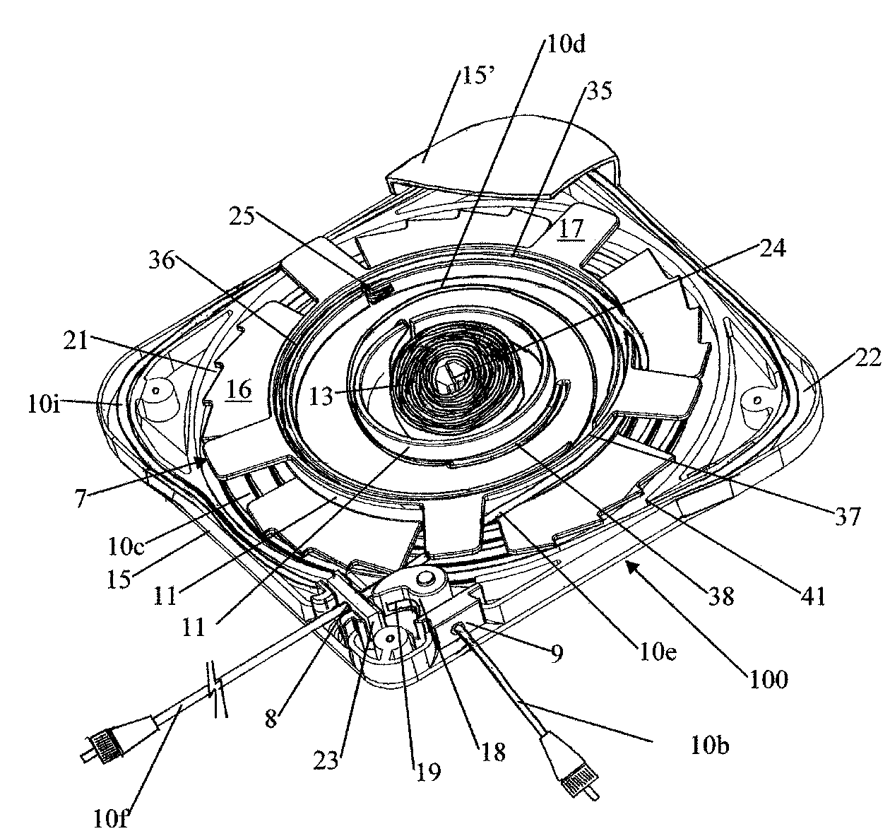
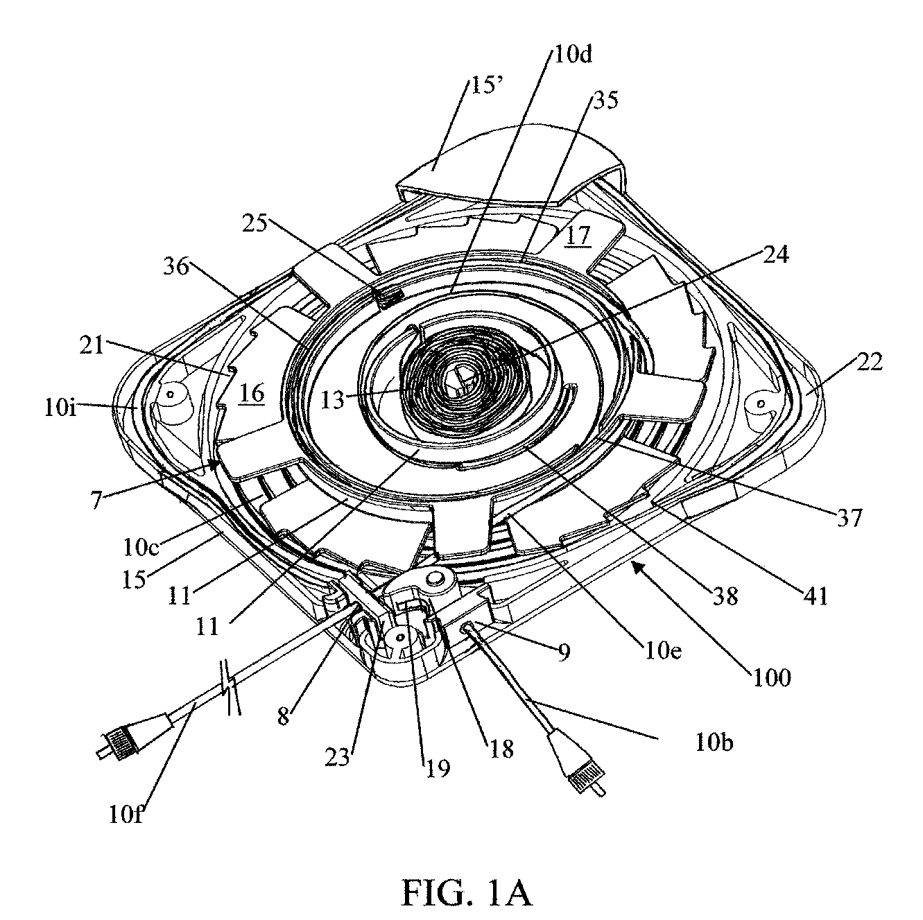
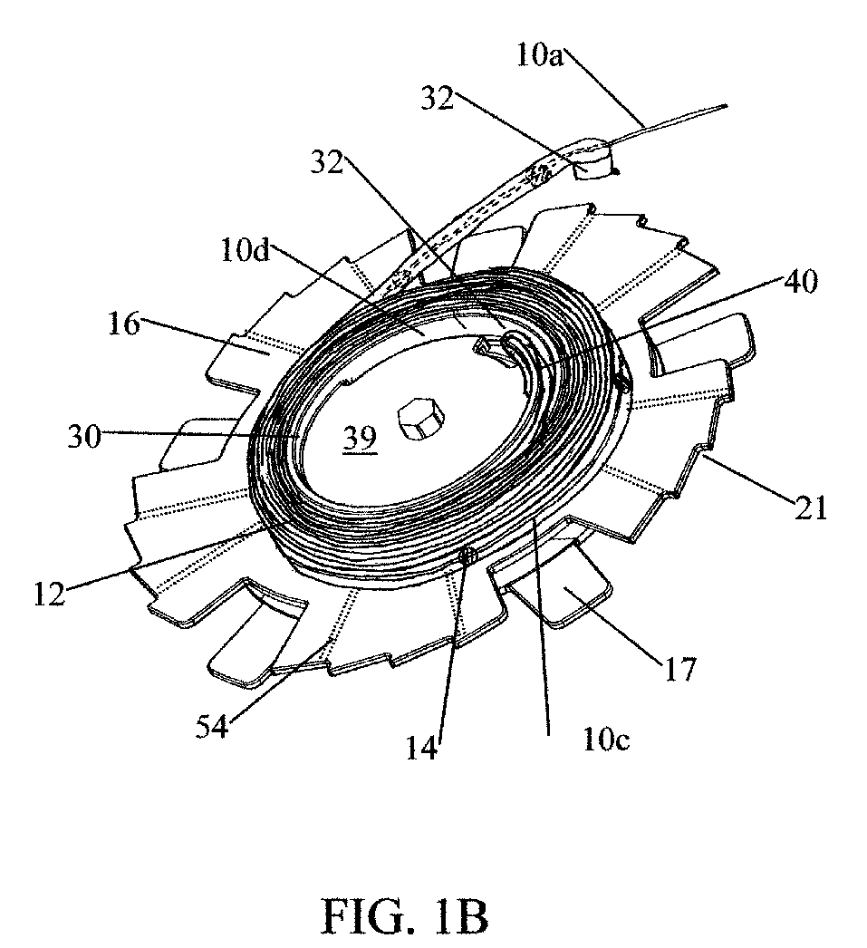
[0026]In this invention we disclose a retractable fiber optic unit which offers high optical performance in a compact and low cost unit. An overview of the structure and operation is desirable because, even though a minimum number of parts are employed, the fiber paths and the geometry are quite complex and not readily understood without use of an excessive number of drawings. This does not seem necessary if the following is appreciated.

[0027]Referring to FIGS. 1 and 2, the expandable / retractable optical fiber cartridge is confined within a lower housing 15 and upper housing 15′ which are generally square in plan view, and which have an exit port 9 for a fixed length of cable and a withdrawal or control port 8 for an extractable, returnable length of cable 10. A central shaft 24 is fixed to the housing and encompassed by a helical power spring 13, one end of which is attached to the shaft 24 and the other end of which is attached to a central spool 7 that is rotatable about the cent...


PUM


Abstract

In this invention, a fiber optic rotary joint and applications of such to retractable fiber optic cables is described. The fiber optic rotary joint consists of a spiral arrangement of a spring and optical fiber pair placed between rotating inner and outer diameters. The fiber optic rotary joint provides a finite number of turns of a fiber optic cable about a primary axis. These turns can be used, for example, with a rotating spool to provide a continuous retractable and extendable cable.

Description

REFERENCE TO RELATED APPLICATIONS[0001]This application relies for priority on provisional application 60 / 599,964 of Anthony Kewitsch, filed on Aug. 9, 2004 and entitled “Retractable Fiber optic Devices,” and provisional application Ser. No. 60 / 638,569 filed on Dec. 22, 2004 and entitled “Fiberoptic Rotary Coupling and Devices.”FIELD OF THE INVENTION[0002]This invention relates to optical systems using fiber optic cables to transmit illumination and / or signals, and more particularly to devices and methods to enable the rotation of opposite ends of a fiber optic cable relative to one another, and further providing a compact means of retracting fiber optic cables.BACKGROUND OF THE INVENTION[0003]The development of improved techniques to manage excess lengths of fiber optic cabling has become particularly relevant with the spread of optical communications technology from the long haul and metro networks to the interconnection rich enterprise and access networks. A unique characteristic...

Claims


Application Information

Patent Timeline
Patent Type & Authority Patents(United States)
IPC IPC(8): G02B6/00
CPCG02B6/4457G02B6/3895G02B6/4453
Inventor KEWITSCH, ANTHONY
Owner TELESCENT
Why Eureka
Try Eureka