
In-situ plasma cleaning device for cylindrical surfaces

a cleaning device and cylindrical surface technology, applied in the direction of diaphragms, metal-working apparatus, metallic material coating processes, etc., can solve the problems of compromising the cleaning process, affecting the adhesion and adhesion of the target material to the cylindrical surface, and requiring a large amount of physical space for storage, so as to eliminate the source of recontamination, the adhesion and coating quality are substantially improved

Inactive Publication Date: 2008-01-22
UNITED STATES OF AMERICA THE AS REPRESENTED BY THE SEC OF THE ARMY
View PDF1 Cites 8 Cited by
  • Summary
  • Abstract
  • Description
  • Claims
  • Application Information

AI Technical Summary

Benefits of technology

[0015]The in-situ plasma cleaning device of the present invention affords a number of advantages over the conventional processes. One such clear advantage is the ability for the in-situ plasma cleaning device to perform cleaning of cylindrical surfaces in a closed volume process that effectively eliminates the source of recontamination as is in the conventional process.
[0016]A further advantage is the ability to tune the locally generated plasma to attain suitable properties for different target and substrate materials. As a result, the adhesion and coating quality is substantially improved over that of a conventional process.
[0017]The modular design of the in-situ plasma cleaning device provides yet another advantage in that the in-situ plasma cleaning device can be adapted to any particular application involving long cylindrical surfaces by simply building the device from a suitable number of target and substrate cleaning assemblies.

Problems solved by technology

In long cylindrical systems, these collector shields would need a large amount of physical space for storage.
As a result of exposure to ambient atmospheric environment, contaminants would be reintroduced back into the cylindrical systems, thereby compromising the cleaning process.
In spite of gas flushing, contamination of cylindrical surfaces still occurs, thus leading to a compromise in the performance of the vacuum system of the ensuing cylindrical magnetron sputtering process.
As a result, coating quality and adhesion of the target material onto the substrate cylindrical surface may be significantly degraded.
Thus, there is currently an unfulfilled need for an improved method of cylindrical surface preparation that will perform the process of cleaning long cylindrical surfaces satisfactorily.

Method used


Image

  • In-situ plasma cleaning device for cylindrical surfaces
  • In-situ plasma cleaning device for cylindrical surfaces
  • In-situ plasma cleaning device for cylindrical surfaces

Examples


Embodiment Construction

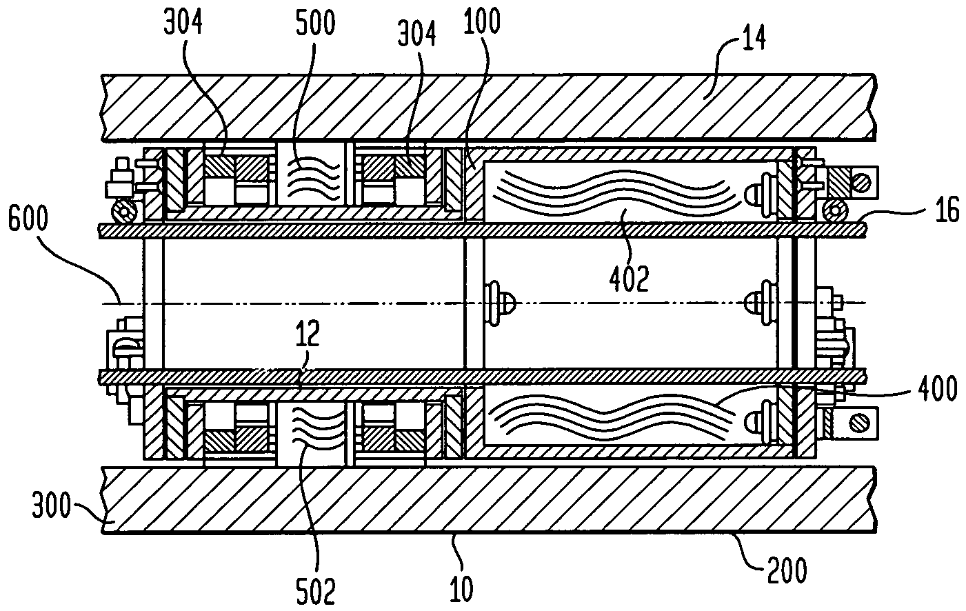
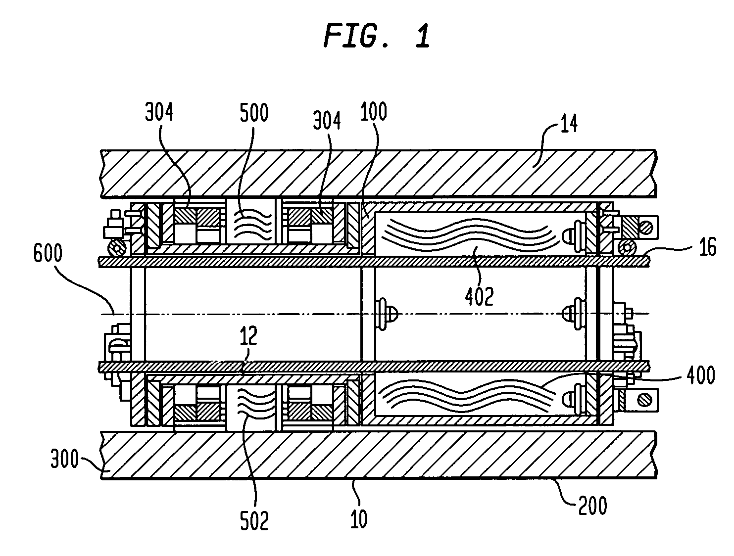
[0043]FIG. 1 illustrates a long cylindrical system 10 comprising of an inner target cylindrical tube 12 and an outer substrate cylindrical barrel 14. The inner target cylindrical tube 12 and the substrate cylindrical barrel 14 are generally concentric and co-located, with the inner target cylindrical tube 12 positioned inside the substrate cylindrical barrel 14.

[0044]Located within the annular space 16 between the inner target cylindrical tube 12 and the substrate cylindrical barrel 14 is an in-situ plasma cleaning device 100 made according to the present invention. FIG. 1 illustrates a preferred embodiment of the in-situ plasma cleaning device 100 of the present invention. In particular, the in-situ plasma cleaning device 100 is comprised of a plurality of target cleaning assemblies 200 and a plurality of substrate cleaning assemblies 300, only one of each is shown in FIG. 1.

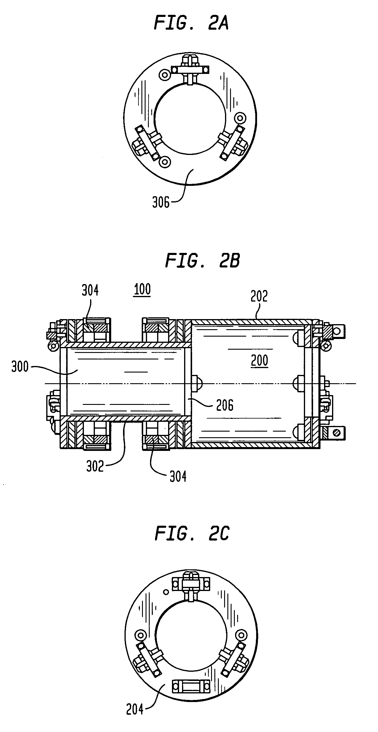
[0045]With reference to FIG. 2, the preferred embodiment of the in-situ plasma cleaning device 100 is shown ...


PUM

PropertyMeasurementUnit
Lengthaaaaaaaaaa
Magnetic fieldaaaaaaaaaa

Abstract

An in-situ plasma cleaning device (PCD) performs an atomic surface cleaning process to remove contaminants and / or to modify the cylindrical surfaces of both the target and substrate. The atomic cleaning process utilizes a plasma generated locally within the in-situ plasma cleaning device with suitable properties to clean both the target and substrate cylindrical surfaces either concurrently or separately. Moreover, the in-situ plasma cleaning device is designed to traverse the length of the target and the substrate cylindrical surfaces during the cleaning process.

Description

FEDERAL RESEARCH STATEMENT[0001]The inventions described herein may be manufactured, used, and licensed by, or for the U.S. Government for U.S. Government purposes.BACKGROUND OF INVENTIONField of the Invention[0002]The present invention relates in general to the field of atomically cleaned surface preparation prior to surface coating, and particularly relates to a new method of removal and / or modification of the contaminant and / or substrate material for preparing long cylindrical surfaces prior to surface coating by cylindrical magnetron sputtering (CMS). More specifically, the invention features an in-situ plasma cleaning device (PCD) that enables the removal and collection of material from either or both target and substrate cylindrical surfaces. Additionally, the ability for the in-situ PCD to be stowed inside the cleaning cylindrical chamber for the application of the CMS coating eliminates the need for exposing the system to ambient atmospheric environment which would introduce...

Claims


Application Information

Patent Timeline
IPC IPC(8): C23C14/34B08B3/00
CPCB08B7/00B08B9/027C23C14/564H01J37/32862
Inventor AUDINO, MICHAEL J.CIPOLLO, MICHAELGLOCKER, DAVIDMINER, KEVINVOTTIS, PATRICK
Owner UNITED STATES OF AMERICA THE AS REPRESENTED BY THE SEC OF THE ARMY
Learn More