Thermally-conductive, electrically non-conductive heat transfer material and articles made thereof

a heat transfer material and non-conductive technology, applied in the field can solve the problems of hardening of heat transfer materials, posed a hazard of electrical shock, and often a problem of electrical conductivity of prior art heat transfer materials, so as to reduce core temperatures and increase power output. , the effect of high conductivity

Inactive Publication Date: 2008-01-22
THERMON INC
View PDF48 Cites 22 Cited by
  • Summary
  • Abstract
  • Description
  • Claims
  • Application Information

AI Technical Summary

Benefits of technology

[0041]Turning to FIG. 6, heat transfer material of the present invention will in many instances replace the present practice of welding of skin-effect heat tubes to process pipes. A skin-effect heat tube 60 is banded to a process pipe 62 by straps 64. A heat transfer material 66 according to the present invention is sandwiched between tube 60 and pipe 62. The advantage of the present invention is that the new jacket material creates a thermal bridge between tube 60 and pipe 62 without physically bonding the tube to the pipe or without the heat transfer material cure-hardening. In the past, prior art materials have not been used due to the potential cracking problems caused by differential thermal expansion between the heat tube and the process pipe. Since heat transfer material 66 remains flexible and does not cure harden, it can accommodate expansion forces without cracking.
[0042]It is anticipated that the new level of flexibility and relatively high conductivity of the jacket material of the present invention will be useful in the construction of electric heat tracing cables. The present heat transfer material will enable self-regulating and power limiting heaters to reduce core temperatures and thus increase power output for a given resistivity level. Such heaters will allow constant wattage wire elements to be surrounded by the heat transfer material of the present invention, which serves as electrical insulation with a thermal conductance that allows an increase in the maximum current levels at which these heaters can safely operate.
[0043]The claimed thermally conductive, electrically non-conductive heat transfer material can be molded onto steam tracing tubes or other heat transfer surfaces, or molded into shapes to be placed on or between heat transfer surfaces, to provide a heat transfer rate in substantially the same range as prior art heat transfer materials of 0.60 to 5.0 BTU / hr-ft-° F. for ⅜″ to ¾″ outside diameter tubes while remaining removable and reusable in service.
[0044]The heat transfer material of this invention has a substantially reduced electrical conductivity over prior art materials, with an electrical resistivity of 1011 ohms-cm or higher service. The heat transfer material is removable, reusable and stable to temperature levels in excess of 450° F. Even after extended operation, the heat transfer material does not cling to or adhere to the underlying heated substrate.
[0045]The heat transfer material of this invention may be used as new electrical insulation for self-regulating, power limiting, and constant wattage electric heat tracing cables. Self-regulating cables have demonstrated increased power output by 7% or more with reduced operating core temperatures. The material utilizes a flexible heat transfer strip material, which may be operated over the range of −60° F. to 450° F. to form thermal bridges between heaters and the heated substrate. The heat transfer material of this invention has greatly improved burn resistance over prior art carbon loaded conductive materials.

Problems solved by technology

This resulted in the heat transfer material hardening and thus permanently and physically bonding the steam tube to the process pipe to which it was mounted.
Since the prior art heat transfer material was electrically conductive, it posed a hazard for electrical shock.
Many other applications also require dielectric jackets, so electrical conductivity of prior art heat transfer materials is often a problem.
Consequently, prior art heating cable was typically not reusable after it was removed from a heated surface because it became hard and brittle during service.
Similarly, heat transfer material that has been extruded onto a steam / fluid tracer tube and installed under a channel typically cannot be subsequently removed and reinstalled without damaging the heat transfer material.
Where heat transfer material has been used between two tubes, which have high expansion forces, the expansion forces have caused the material to crack.

Method used


Image

  • Thermally-conductive, electrically non-conductive heat transfer material and articles made thereof
  • Thermally-conductive, electrically non-conductive heat transfer material and articles made thereof
  • Thermally-conductive, electrically non-conductive heat transfer material and articles made thereof

Examples


example 1

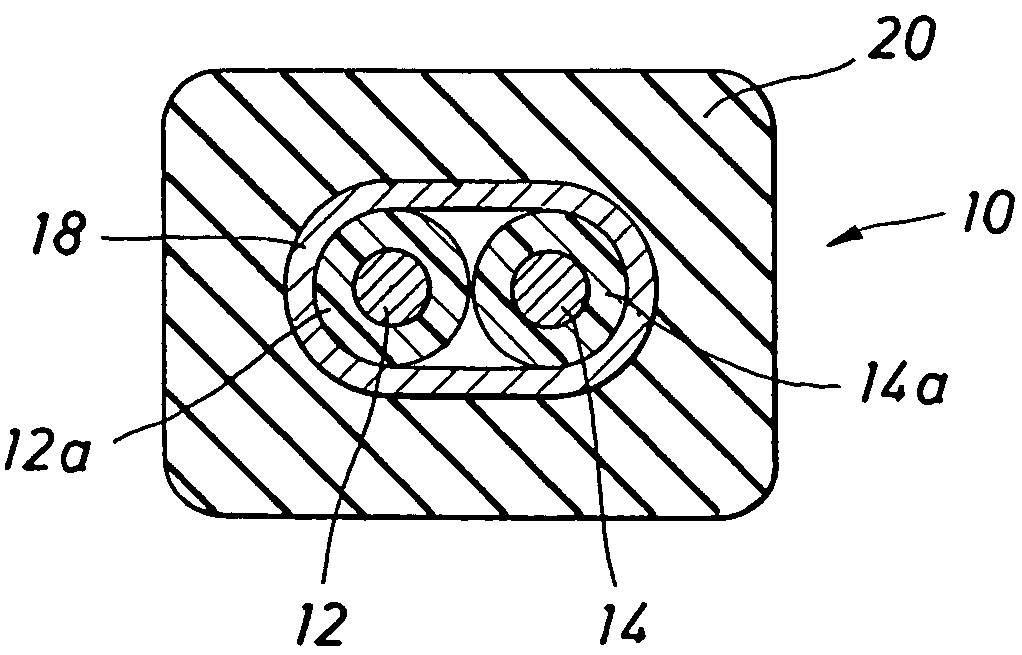
[0046]A TEK 3C40 BN cable sample (from Thermon Manufacturing Co. of San Marcos, Tex., U.S.A.) with a conductive silicone jacket according to the present invention was tested on an 85 lb. composite rail. The purpose of this study was to investigate the heat transfer characteristic of the thermally conductive silicone jacketed cable and compare results with a regular (thermally non-conductive) silicone jacketed cable. The cable has an electrically conductive braid of copper wires and a jacket covering the wires, such as shown in FIG. 1.

[0047]An 8.83 foot long TEK 3C40 BN cable sample with thermally conductive silicone jacket was tested on a 8.66 foot long 85 lb. composite rail. A control cable sample (regular silicone jacket) of identical length was also tested. Cable samples were tested at 5, 10, 15, and 20 watts per foot at ambient temperature of approximately 5° F. The rail assembly was tested in a cold chamber.

[0048]Very significant temperature reductions (over standard silicone f...

example 2

[0049]A RDT 40-600 BN cable sample from Thermon Manufacturing Co. with a thermally conductive silicone jacket was tested on an 85 lb. composite rail. The heat transfer characters of thermally conductive silicone jacketed cable was compared to that of a regular silicone, SureFlow (SFOJ), jacketed cable.

[0050]An 8.83 foot long RDT 40-600 BN cable sample with conductive silicone jacket was tested on a 8.66 foot long 85 lb. composite rail. A control cable sample (regular BNSF jacket) of identical length was also tested. J-type thermocouples were located on the cable, jacket, and rail. Cable samples were tested at 5, 10, 20, 30 and 40 watts per foot at an ambient temperature of approximately −6° F. The rail assembly was tested in a cold chamber. The sheath and jacket temperatures were also measured for cable away from the rail. Test results are summaries in Tables 1 and 2. The temperature difference or delta T between the sheath and the jacket is lower for DT 40-600 BN thermally conducti...

example 3

[0053]Volume resistivity for an insulating material is used to predict the dielectric breakdown of the materials. Volume resistivity was determined for conductive silicone of the present invention, silicone rubber, and graphite loaded heat transfer cement.

[0054]Volume resistivity was measured on test samples per ASTM standard D257. A Model 1864 megOhm meter manufactured by General Radio was used for volume resistivity measurements on test samples. Terminal 1 was tied to the − unknown terminal, terminal 2 to the guard, and terminal 3 to the + unknown terminal. Volume resistance was measured at 500 volts for thermally conductive silicone and silicone rubber samples. Volume resistance for graphite loaded heat transfer cement was measured at 60 volts because volume resistance could not be measured at 500 volts as heat transfer cement was too conductive for this measurement at voltage above 70 volts.

[0055]Volume resistivity was calculated from measured volume resistance in ohms, the effe...


PUM

PropertyMeasurementUnit
temperatureaaaaaaaaaa
temperaturesaaaaaaaaaa
temperatureaaaaaaaaaa

Abstract

A heat transfer material comprised of a polymeric material and a nitride or oxide is provided and is thermally conductive, but electrically non-conductive. The polymeric material may be silicone rubber, and the nitride or oxide may be aluminum nitride, boron nitride, silicon nitride, aluminum oxide or beryllium oxide. The material is made flexible by adding plasticizer and remains flexible after an extended period of use. A dielectric jacket for an electrical heating cable is thermally conductive and remains flexible so that it can be reused. The heat transfer material can be used on heating devices such as steam tubes and panels, where the heat transfer material does not bond to or adhere to the heated surface, which allows the heating device to be reused.

Description

CROSS-REFERENCE TO RELATED APPLICATIONS[0001]This application is a continuation of U.S. application Ser. No. 10 / 165,441, filed Jun. 7, 2002, now U.S. Pat. No. 6,762,395, which is a divisional of U.S. application Ser. U.S. No. 09 / 353,675, filed Jul. 15, 1999, now U.S. Pat. No. 6,410,893, which claims priority to U.S. Provisional patent application No. 60 / 092,943, filed Jul. 15, 1998. This application claims the benefit of and priority to each of these prior applications, all of which are herein incorporated by reference in their entirety for all purposes.STATEMENTS REGARDING FEDERALLY SPONSORED RESEARCH OR DEVELOPMENT[0002]Not applicable.REFERENCE TO A MICROFICHE APPENDIX[0003]Not applicable.BACKGROUND OF THE INVENTION[0004]1. Field of the Invention[0005]The present invention relates generally to heat transfer material and more particularly to one that is thermally conductive, but electrically non-conductive. Articles made with the material include a dielectric jacket for a heating c...

Claims


Application Information

Patent Timeline
Patent Type & Authority Patents(United States)
IPC IPC(8): H05B3/06C08K3/22C08K3/28
CPCC08K3/22C08K3/28C08L83/04
Inventor YAGNIK, CHANDRAKANT M.BARTH, ROY E.PITZER, R. KNOX
Owner THERMON INC
Why Eureka
Try Eureka