Gas storage canister

a technology of gas storage canister and canister, which is applied in the direction of machines/engines, separation processes, combustion air/fuel air treatment, etc., can solve the problems of substantially difficult to obtain both effects, uneven temperature distribution of the canister during adsorption and desorption of vapor, etc., and achieve the effect of improving the adsorption ra

Active Publication Date: 2008-01-29
OSAKA GAS CO LTD
View PDF10 Cites 32 Cited by
  • Summary
  • Abstract
  • Description
  • Claims
  • Application Information

AI Technical Summary

Benefits of technology

[0007]Therefore, it is an object of the present invention is to provide an improved gas storage canister which can effectively overcome drawbacks encountered in conventional gas storage canisters.
[0009]A further object of the present invention is to provide an improved gas storage canister which accomplishes suppression of temperature rise due to adsorption of latent heat and suppression of temperature drop due to release of latent heat in such a manner as to make a temperature distribution uniform inside the gas storage canister.

Problems solved by technology

Therefore, the temperature distribution of the canister during the adsorption and desorption of vapor is not uniform.
Therefore, it is substantially difficult to obtain both effects, i.e. a temperature rise suppressing effect during the adsorption of vapor and a temperature drop suppressing effect during the desorption of vapor.

Method used


Image

  • Gas storage canister
  • Gas storage canister
  • Gas storage canister

Examples


example 1-1

[0061]A 37% formaldehyde aqueous solution in an amount of 6.5 g and water in an amount of 10 g were added to 5 g of powdered melamine to form a mixture. The mixture was adjusted to have a pH of 8, and then heated to about 70° C. thereby obtaining a melamine-formaldehyde initial-stage condensation product.

[0062]A mixture solution was prepared by dissolving 80 g of n-eicosane serving as a phase changing material into 100 g of a sodium salt aqueous solution of stylene-maleic anhydride copolymer which solution had been adjusted to pH 4.5. This mixture solution was added to the above melamine-formaldehyde initial-stage condensation product while being vigorously stirred thereby making emulsification, followed by a pH adjustment to pH 9, thus accomplishing a micro-encapsulation to form micro-capsules dispersed in the solution. Thereafter, solvent of the solution in which the micro-capsules were dispersed was removed upon being dried thus obtaining powdered bodies or micro-capsules (heat a...

example 1-2

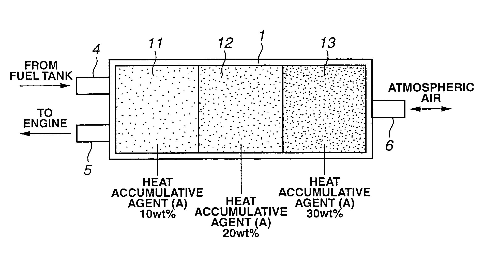
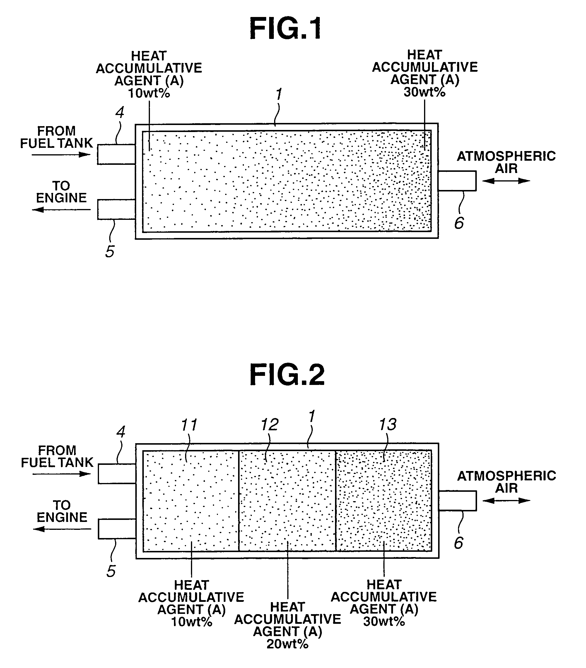
[0067]The mix proportion of the same formed heat accumulative agent (A) and that of the formed activated carbon as were used in Example 1-1 were varied in a stepped manner so that the interior of the case 1 is partitioned into three regions in the direction of flow as shown in FIG. 2. A uniform mixture of 10 wt % of formed heat accumulative agent (A) and 90 wt % of formed activated carbon was packed in a first region 11 on the side of the vapor inflow port 4 and vapor outflow port 5, and a mixture of 20 wt % of formed heat accumulative agent (A) and 80 wt % of formed activated carbon was packed in a second region 12 in a central portion of the case. A uniform mixture of 30 wt % of formed heat accumulative agent and 70 wt % of formed activated carbon was packed in a third region 13 on the side of the atmosphere-opened port 6.

example 1-3

[0081]As shown in FIG. 12, formed activated carbon only was packed in a gas adsorbing material housing space 10a in a U-shaped canister, and a mixture of formed heat accumulative agent (A) and formed activated carbon was then packed in a second adsorbing material housing space 10b. Especially, at the end portion of the second adsorbing material housing space 10b at the side of a communication passage (space 36) which communicates with the first gas adsorbing material housing space 10b, formed heat accumulative agent (A) became 0 wt %, and formed activated carbon 100 wt %; at an end portion on the side of the atmosphere-opened port 6, formed heat accumulative agent (A) became 40 wt %; and formed activated carbon 60 wt % so that the mix proportion of the formed heat accumulative agent (A) at the two end portions varied continuously. Therefore, an average mix proportion in the canister as a whole became 10 wt % of formed heat accumulative agent (A) and 90 wt % of formed activated carbo...


PUM


Abstract

A gas storage canister for use in an automotive vehicle, includes a case having first and second end sections which are opposite to each other in a direction of flow of gas. The first end section has a gas inflow port and a gas outflow port. The second end section has an atmosphere-opened port. A gas adsorbing material is disposed inside the case. Additionally, a heat accumulative agent is provided including a phase changing material which causes absorption and release of latent heat to occur in accordance with a temperature variation. The heat accumulative material is mixed with the gas adsorbing material and disposed inside the case. Here, a mix proportion of the heat accumulative agent changes in the gas flow direction between the first and second end sections.

Description

BACKGROUND OF THE INVENTION[0001]This invention relates to improvement in a gas storage canister, for example, using activated carbon or the like in order to treat fuel vapor of an automotive internal combustion engine.[0002]In an automotive internal combustion engine for instance, a gas storage canister is provided to be able to store and release fuel vapor for the purpose of preventing fuel vapor generated in a fuel tank from releasing out of an automotive vehicle. Fuel vapor generated, for example, after a vehicle stopping is temporarily stored in the gas storage canister and is released together with fresh air from the gas storage canister to be introduced into the engine when the engine is operated after the vehicle stopping. Here, the following fact is known: In the gas storage canister using a gas adsorbing material such as activated carbon or the like, an exothermic reaction occurs when fuel vapor is adsorbed to the gas adsorbing material, so that the temperature of the gas ...

Claims


Application Information

Patent Timeline
Patent Type & Authority Patents(United States)
IPC IPC(8): B01D53/02F02M25/08
CPCF02M25/0854F02M25/0836F02M2025/0845F02M2025/0881
Inventor YOSHIDA, HIROYUKIYAMAZAKI, KOJI
Owner OSAKA GAS CO LTD
Why Eureka
Try Eureka