
Thermal pellet incorporated thermal fuse and method of producing thermal pellet

a technology of thermal fuse and thermal pellet, which is applied in the direction of thermally actuated switches, electric switches, electrical apparatus, etc., to achieve the effects of high response speed, quick response ability, and reduced production costs

Active Publication Date: 2008-01-29
SCHOTT JAPAN CORP
View PDF67 Cites 25 Cited by
  • Summary
  • Abstract
  • Description
  • Claims
  • Application Information

AI Technical Summary

Benefits of technology

The present invention provides a thermal pellet incorporated thermal fuse that can operate at a desired temperature with high precision and response speed. The thermal fuse includes a thermal pellet formed of a high molecular weight substance that can thermally deform at a prescribed temperature. The thermal pellet is adjusted in degree of thermal deformation by a temperature setting method to be the desired operating temperature for use. The thermal fuse is enclosed in a cylindrical enclosure and includes a first lead member and a second lead member to form electrodes. A movable conductive member is engaged with the thermal pellet and a spring is exerted on the movable conductive member to switch an electric circuit between the electrodes. The thermal fuse is formed of a thermosensitive material that can thermally deform at a desired operating temperature. The method of setting a temperature ensures the thermal fuse's operating temperature is set with high precision. The thermal fuse is usable at high temperatures and is stable and reliable. The invention provides a solution for incorporating a thermal fuse into a thermal pellet for improved performance and reliability.

Problems solved by technology

If the thermosensitive material is of a high molecular weight substance, however, it introduces a problem in setting an operating temperature and this needs to be solved to allow the fuse to operate with improved precision.

Method used


Image

  • Thermal pellet incorporated thermal fuse and method of producing thermal pellet
  • Thermal pellet incorporated thermal fuse and method of producing thermal pellet
  • Thermal pellet incorporated thermal fuse and method of producing thermal pellet

Examples


example 1

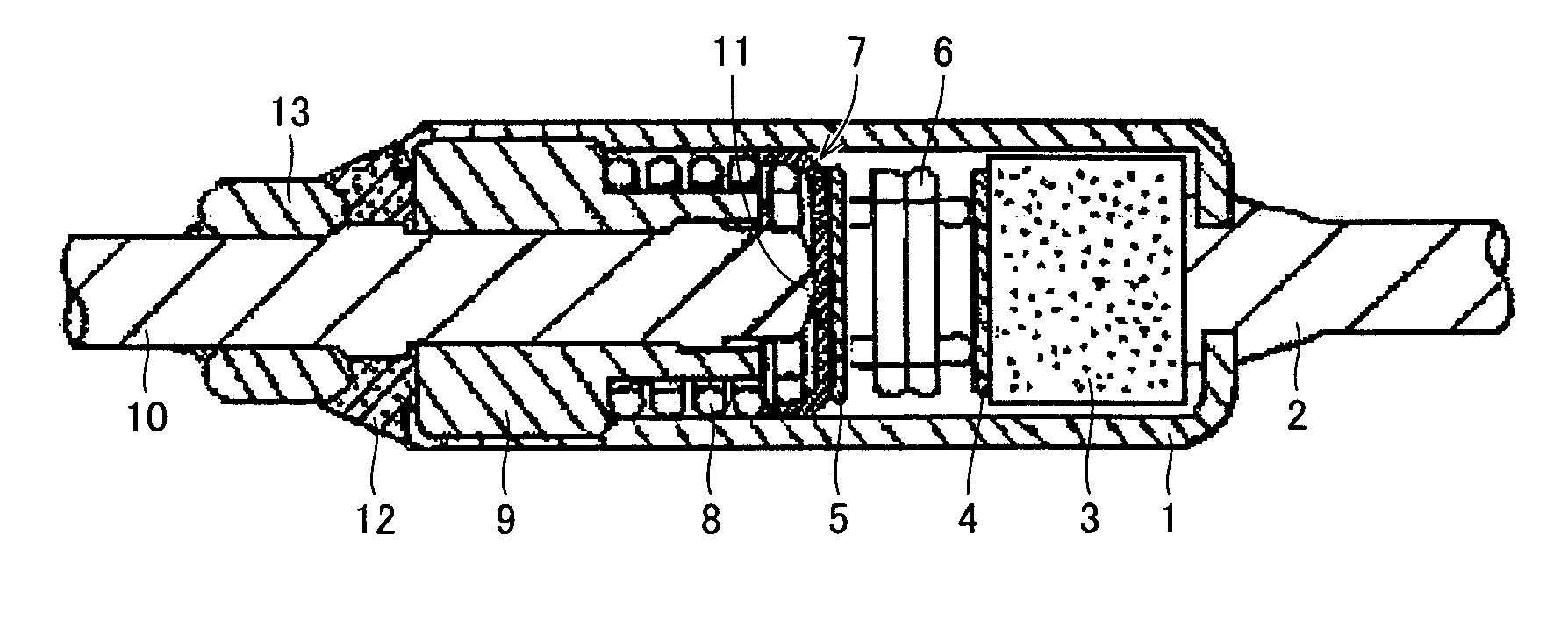
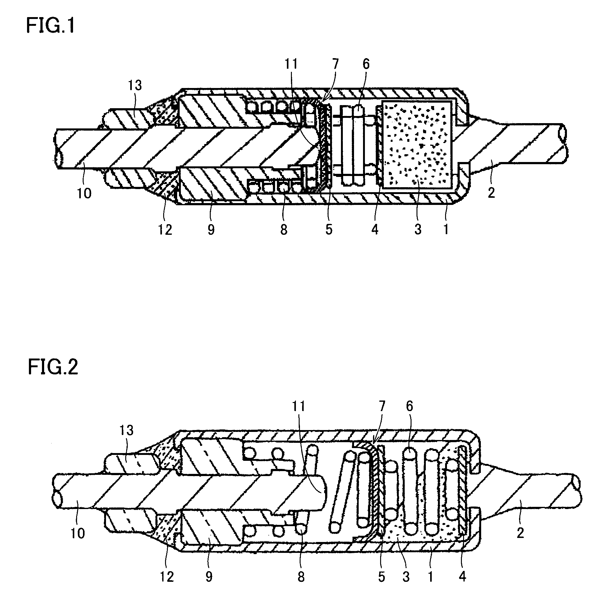
[0059]FIGS. 1 and 2 each show a cross section of a thermal pellet incorporated thermal fuse of the present embodiment. FIG. 1 is a cross section thereof at normal time at normal temperature and FIG. 2 is a cross section thereof in operation when it experiences abnormal heat. This configuration is similar in basic structure to a thermal pellet incorporated thermal fuse SEFUSE® produced by NEC SCHOTT Components Corporation except for material used for thermosensitive material. A cylindrical enclosure 1 is a casing formed of copper, yellow copper or similar satisfactorily heat conductive metal and having one opening with a first lead member 2 crimped and thus fixed thereto. Metal casing 1 accommodates a thermal pellet 3, a feature of the present invention, together with a component functioning as a switch including a pair of pressure plates 4 and 5, a spring member including strong and weak compression springs 6 and 8, and a movable conductive member 7 formed of silver alloy satisfacto...

example 2

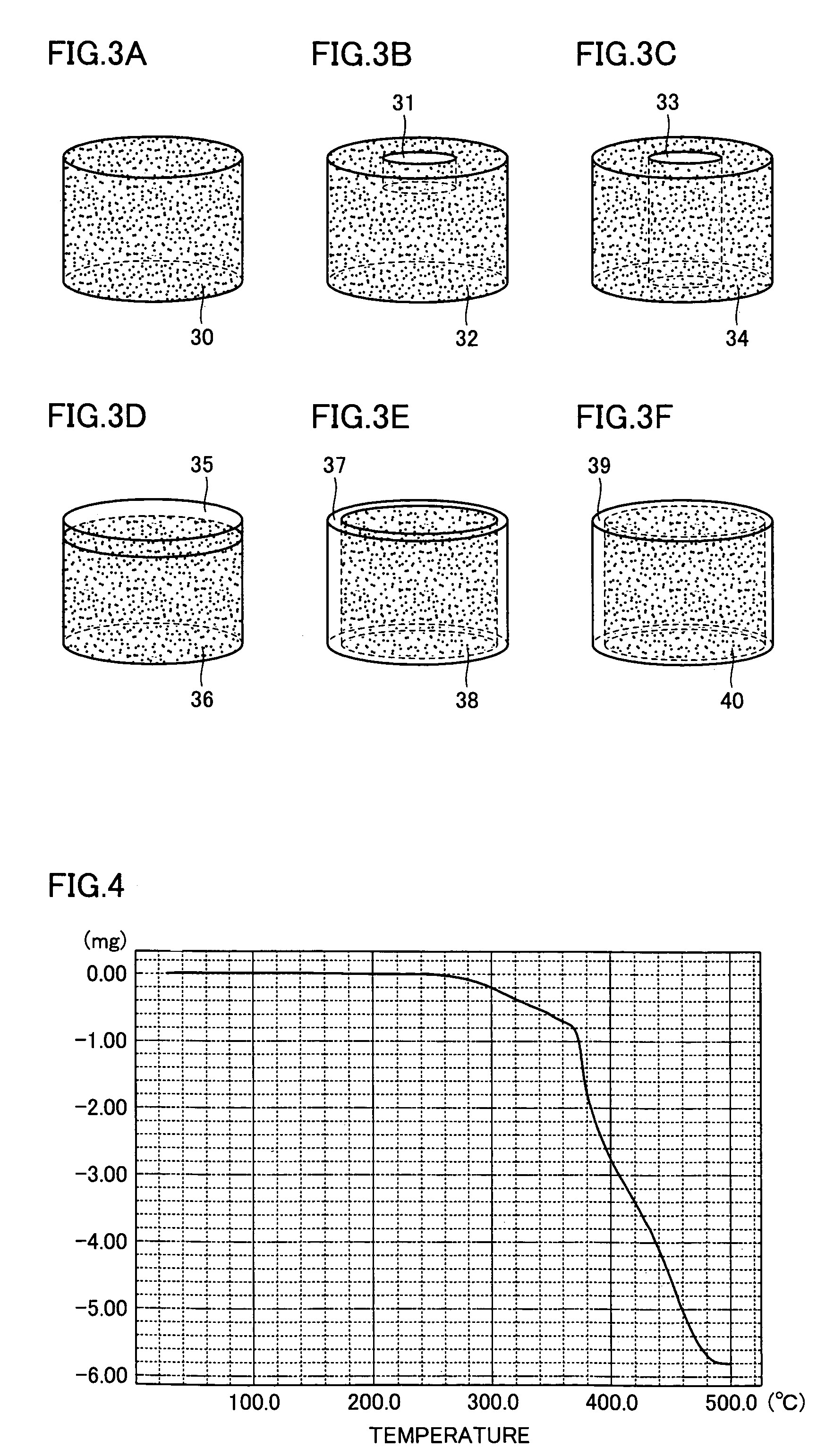
[0081]An experiment is conducted on exemplary variations in geometry of thermal pellet 3 of the FIG. 1 thermal pellet incorporated thermal fuse, and for examining their functions and effects. Thermal pellet 3 typically has a substantially columnar structure, and a variety of exemplary variations thereof, as shown in FIG. 3, are evaluated. In accordance with the present invention, heat distortion temperature is set by a method including a method setting a special geometry, and this method is effective in adjusting an operating temperature as desired. FIG. 3 shows thermal pellets having six different geometries. FIG. 3A shows a general purpose, substantially columnar pellet 30. A substantial column can satisfactorily be incorporated in comparison with a quadrangular prism, and by modifying the column in length and diameter an operating temperature can be set as desired. FIG. 3B shows a pellet 32 provided with a recess 31. FIG. 3C shows a pellet 34 hollowed or provided with a cavity 33...

example 3

[0083]Thermoplastic resin employed in the present embodiment is used to form thermal pellet 3 to fabricate the FIG. 1 thermal pellet incorporated thermal fuse, and the fuse's operating temperature and variation (precision of operation: R) are indicated in Table 6. Furthermore, Table 7 indicates an insulation resistance value as an electrical characteristic for high temperatures of 350° C. and 400° C. In Table 7, “O” indicates an insulation resistance value of at least 0.2 MΩ at least for one minute and “X” indicates an insulation resistance value of less than 0.2 MΩ within one minute.

[0084]

TABLE 6unit (° C.)Conventional ProductsProductOperatingAtProductThermal Fuse Incorporating The Present Thermal PelletProduct113° C.OperatingPOMOperating3,5-At 192° C.RETLDPELLDPEHDPEF20-PPPBTPMPFEPAt 110° C.dimethyl4-methylNo.ET182JM910NAM830A1300J54J557F310RT18NP-101resorcinpyrazoleumbelliferone1101.2109.1125.8131.7163.3170.8227.6236.0268.3109.4112.3190.02101.7108.9125.6131.7163.3170.7227.4236.02...


PUM

PropertyMeasurementUnit
temperatureaaaaaaaaaa
insulation resistanceaaaaaaaaaa
temperatureaaaaaaaaaa

Abstract

A thermal fuse incorporating a thermal pellet has its operating temperature, or heat distortion temperature, adjusted and the thermosensitive material of the pellet avoids deformation, modification or similar deficiency if it is exposed to a severe external environment. The inexpensive thermal fuse provides a wider range from which an operating temperature can be selected, improved insulation resistance after operation, faster response speed in operation, and enhanced strength of the thermal pellet. The thermosensitive material is formed of a thermoplastic resin corresponding to a high molecular weight substance. The thermal pellet's heat distortion temperature is adjusted by a temperature setting method. An enclosure of the fuse has a metal casing with a spring member's strong and weak compression springs both accommodated therein and hermetically sealed.

Description

BACKGROUND OF THE INVENTION[0001]1. Field of the Invention[0002]The present invention relates generally to thermal pellet incorporated thermal fuses and methods of producing thermal pellets used therefor, and particularly to thermal pellet incorporated thermal fuses employing thermoplastic resin as a thermosensitive material.[0003]2. Description of the Background Art[0004]A thermal fuse is generally classified into two types depending on the thermosensitive material used: a thermal pellet incorporated thermal fuse employing a non-conductive thermosensitive substance; and a thermal fuse using fusible alloy employing a conductive, low melting alloy. They are both a so-called, non-revertive thermal switch operating at a prescribed temperature to interrupt an electric current of equipment, apparatuses and the like or allow a conduction path to conduct to protect them as the surrounding temperature increases. It operates at a temperature determined by the thermosensitive material used. T...

Claims


Application Information

Patent Timeline
Patent Type & Authority Patents(United States)
IPC IPC(8): H01H85/06H01H85/055H01H37/76H01H69/02H01H85/02
CPCH01H37/765H01H2037/769H01H2037/768H01H85/02
Inventor YOSHIKAWA, TOKIHIRO
Owner SCHOTT JAPAN CORP
Learn More