Device and a method for magnetizing a magnet system

a magnet system and magnetization technology, applied in the direction of electromagnets, inductances, electromagnets without armatures, etc., can solve the problems of affecting the efficiency of magnetization, and unable to achieve high cycle frequency, etc., to achieve high cycle rate and high productivity

Active Publication Date: 2008-01-29
MAURER MAGNETIC
View PDF16 Cites 11 Cited by
  • Summary
  • Abstract
  • Description
  • Claims
  • Application Information

AI Technical Summary

Benefits of technology

[0011]It is one object of this invention to specify a method and a device for magnetization of permanent magnets which do not have the disadvantages previously mentioned. The method and device of this invention should permit permanent magnets of rare-earth materials to be magnetized in large-scale manufacture with a high cycle rate of one second or less, and thus ensure a high productivity. The method and the device of this invention should be suitable for application in an automatic production installation, and also permit the magnetization of magnets which have been bandaged on rotors, and should operate in an energy-saving manner and operate with air-cooling. The device should be compact, robust, as well as inexpensive and, where possible, employ standard components.
[0017]In another embodiment of the device according to this invention, the pulse-generator circuit is present in a multiple manner, for example four-fold to twelve-fold, which in the following is indicated as a “parallel multiplication” or “parallelization” of the pulse-generator circuit. With the parallel multiplication, the inductance of the magnetization coil and the capacitance of the capacitor element in the oscillation circuit may be kept small. The demanded short pulse durations of 100 μs, for example, thus result. Despite this, sufficiently large magnetic fields are produced which can magnetize modern, demanding magnet systems.
[0018]For a reduction of the heat energy which is released in the magnetization coil, the magnetization pulse is limited in duration. The usual discharge circuit with a recovery diode transfers a considerable share of the impulse energy stored in the capacitor at the exponentially decaying end of the pulse. This section however no longer has any magnetizing effect. With a new type of circuit which has an accumulating inductor coil in the path of the recovery diode, the exponential decay of the current in the magnetization coil can be suppressed and the energy which is contained therein, to a great extent, may be recovered. The inductive return permits the second reoscillation of the capacitor voltage and thus prevents ohmic losses by way of dying-out oscillations. The remaining energy charges the capacitor element again for the next pulse. A reduced energy consumption is thus achieved, and an expensive cooling of the coil is no longer necessary. The second reoscillation via the inductive return, with a fourfold parallelization of the magnetization coil, results in an additional energy saving of 43%. Without parallelization, with a single magnetization coil and the same power, this figure is only 18%.

Problems solved by technology

With this, the magnetization coil is heated to an undesirable extent, which renders a high cycle frequency impossible and necessitates the application of expensive cooling systems.
Permanent magnets of rare-earth metals such as neodymium-iron-boron (NdFeB) are now taking the place of the ferrite magnets which are applied in large numbers and are considerably more difficult to magnetize because of their high coercive force.
Air-core coils must be used for magnetization and have a considerably worse efficiency on magnetization because the magnetic field may not be concentrated on the magnets.
Thus, considerably higher outputs need to be brought into the coil, and their undesired heating is accordingly higher.
This technology is suitable for individual magnetizations in the laboratory and in the field of manufacture, but not for large-scale manufacture.
In large-scale manufacture there is not sufficient available time for cooling the magnetization coil between the individual magnetization procedures.
For modern permanent magnets with a high coercive force the power of such a magnetization installation is limited in large-scale manufacture.
With a restricted space for the magnetization coil, the magnets in the assembled condition may hardly be magnetized with conventional methods.
In this case, previously magnetized permanent magnets are installed into the magnet system, which places particular demands on the assembly.
The handling of magnetized permanent magnets and magnet systems is awkward because ferromagnetic particles of all types are attracted and may hardly be removed again.
The same is the case with the peeling or spalling of the magnet which inevitably results when there is impact of the permanent magnets.
This arrangement requires an expensive cooling and consumes much energy.
The magnetization coil of a high-temperature superconductor is expensive and is prone to malfunctioning.
A magnetization of pre-assembled magnets may not be achieved with this device.

Method used


Image

  • Device and a method for magnetizing a magnet system
  • Device and a method for magnetizing a magnet system
  • Device and a method for magnetizing a magnet system

Examples


Embodiment Construction

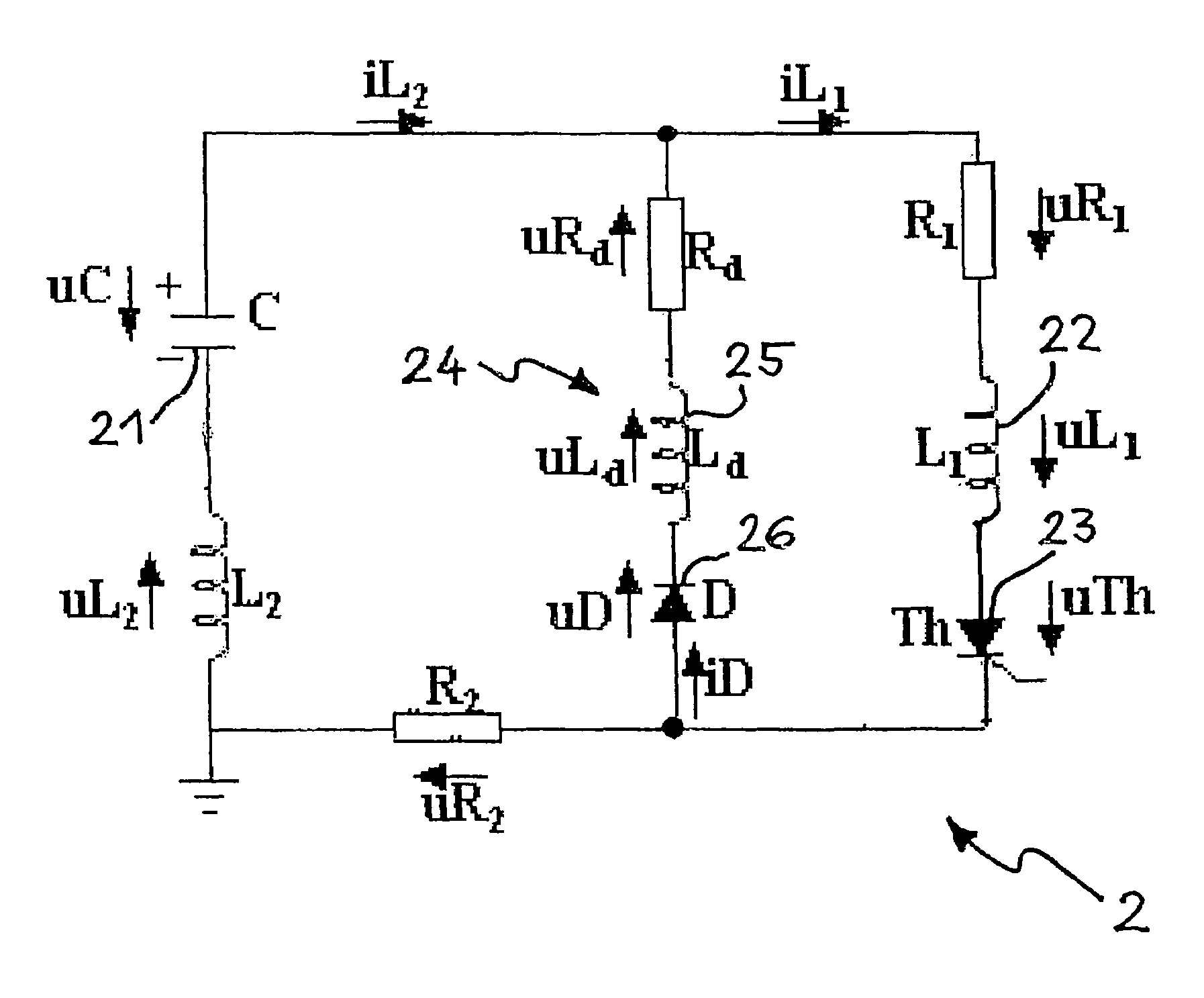
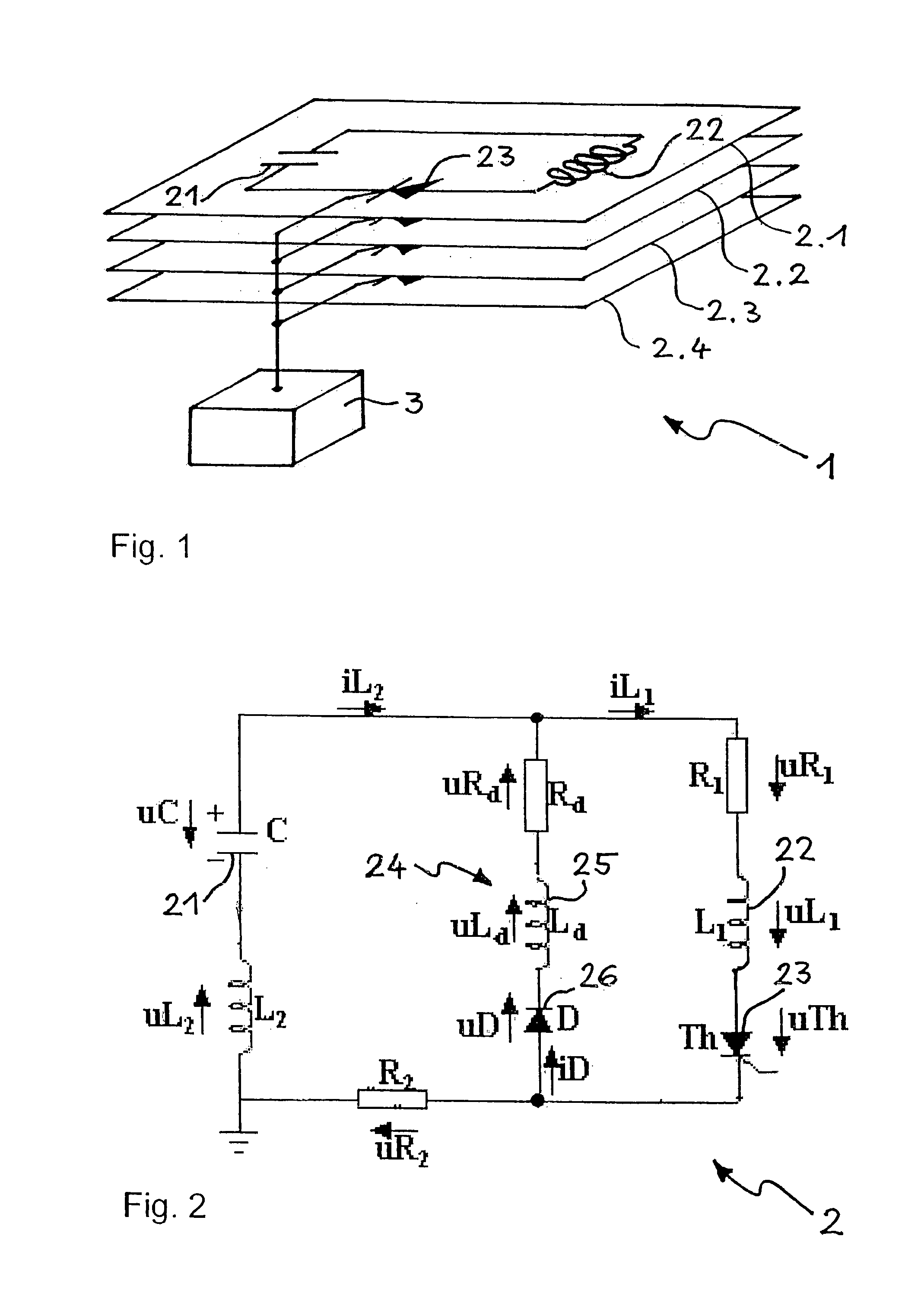
[0029]Important elements of one embodiment of a device 1 according to this invention are shown schematically in FIG. 1. The device 1 comprises several, preferably identical pulse-generator circuits 2.1-2.4. Four pulse-generator circuits 2.1-2.4 are shown in the embodiment of FIG. 1. There may however be more or less. Each pulse-generator circuit 2.1-2.4 comprises a capacitor element 21, preferably a foil capacitor, and a magnetization coil 22 electrically connected to the capacitor element 21. Each pulse-generator circuit 2.1-2.4 further comprises a switch element 23, for example a thyristor, on whose actuation a pulse-like discharge of the capacitor element 21 via the magnetization coil 22 may be activated, and thus the build-up of a magnetic field in the magnetization coil 22. The device 1 also comprises actuation means or an actuator 3 from which the switch elements 23 of the at least two pulse-generator circuits 2.1-2.4 may be simultaneously actuated. Actuators are known to thos...


PUM

PropertyMeasurementUnit
magnetizationaaaaaaaaaa
voltagesaaaaaaaaaa
inductance L1aaaaaaaaaa

Abstract

A device for magnetizing a magnet system preferably having several pulse-generator circuits which are mutually arranged so that their magnetic fields superimpose in a cumulative manner. Each pulse-generator circuit includes a capacitor element, a magnetization coil electrically connected to the capacitor element and a switch element by way of which actuation the magnetization coil can be impinged with a current pulse of a limited pulse duration arising by the discharge of the capacitor element, and thus the build-up of a magnetic field may be triggered. The pulse-generator circuit is built up so that the pulse duration of the current pulse is limited to a value between 10 μs and 500 μs. With such short pulse durations, undesirable heating of the magnetization coil is short so that the device may be applied in automatic production installations with cycle times of below 1 s.

Description

BACKGROUND OF THE INVENTION[0001]1. Field of the Invention[0002]This invention relates to a method and a device for magnetizing a magnet system and, for example, is suitable for magnetizing and magnetically anchoring permanent magnets of rare-earth materials on the rotor of an electric motor which may be applied in automatic magnetization installations with low cycle times or with large-scale manufacture.[0003]2. Discussion of Related Art[0004]It is known to use a magnetization coil for magnetizing permanent magnets. The magnetization coil is arranged directly above or around the magnet body to be magnetized. A charged capacitor is allocated to the magnetization coil and the capacitor is discharged via the coil. The magnetic field, which is built up for a brief period in the magnetization coil, magnetizes the magnet body. In order to build up a sufficiently large magnetic field one must use a magnetization coil with many windings or with a large inductance. The usual pulse durations...

Claims


Application Information

Patent Timeline
Patent Type & Authority Patents(United States)
IPC IPC(8): H01H47/00H01F7/18H01F13/00H01F17/00
CPCH01F13/003H01F7/1816H01F17/0013
Inventor MAURER, ALBERTMEYER, URSHAAS, STEFANMUELLER, OLIVIER
Owner MAURER MAGNETIC
Why Eureka
Try Eureka