Control system for catalytic processes

a control system and catalytic technology, applied in the direction of machines/engines, hydrogen isotopes, bulk chemical production, etc., can solve the problems of carbon monoxide interference with the catalytic mechanism, poisoning of catalysts, carbon deposition,

Inactive Publication Date: 2008-02-05
PAPPAS PETER D
View PDF25 Cites 14 Cited by
  • Summary
  • Abstract
  • Description
  • Claims
  • Application Information

AI Technical Summary

Benefits of technology

[0012]According to the present invention, there is a control system for a catalytic process. The control system comprises the following: a) an electroconductive support having a layer of a catalyst thereon; b) a means for applying DC current of one polarity to the catalyst layer and the opposite polarity to the electroconductive support; c) a means for controlling and varying the application of DC current; d) a means for measuring the polarization impedance across the catalyst layer and the electroconductive support; e) a means for comparing the measured polarization impedance with a reference value; and f) a means for varying the application of DC current to the catalyst layer and the electroconductive support when the measured polarization impedance differs from the reference value. The control system may further optionally comprise the following: g) a means for heating the electroconductive support; h) a means for controlling and varying the application of heat; and i) a means for varying the application of heat to the catalyst and the electroconductive support when the measured polarization impedance differs from the reference value.
[0013]Further according to the present invention, there is a control system for a catalytic process. The control system has an electroconductive support having a layer of a catalyst thereon. A current control unit communicates with a first electrode and a second electrode opposite in polarity to the first electrode. The current control unit controls and varies the application of DC current to the first and second electrodes. The first electrode is in contact with the electroconductive support. The second electrode is in contact with the catalyst. The current control unit controls and varies the application of an AC current to the first and second electrodes. An AC sensor is in communication with the catalyst layer or the electroconductive layer. The level of AC current in the first and second electrodes and the level of AC current detected at the AC sensor at two different frequencies is communicated to an impedance measurement unit where polarization impedance is determined. The impedance measurement unit communicates with a central processing unit wherein the measured polarization impedance is compared to a reference value. The central processing unit communicates with the current control unit to vary the application of DC current to the first and second electrodes when the determined polarization impedance differs from the reference value.
[0014]Still further according to the present invention, there is a control system for a catalytic process. The control system has a) first and second system components each having an electroconductive support having a catalyst layer thereon wherein the catalyst layers are spaced-apart from, in proximity to, and oriented toward each other; b) a means for applying a DC field across the two catalyst layers; c) a means for controlling and varying the application of the DC field; d) a means for measuring the polarization impedance across the two catalyst layers; e) a means for comparing the measured polarization impedance with a reference value; and f) a means for varying the application of the DC field across the two catalyst layers when the measured polarization impedance differs from the reference value.
[0015]Further yet according to the present invention, there is a control system for a catalytic process. The control system has first and second system components each having an electroconductive support having a catalyst layer thereon wherein the catalyst layers being spaced-apart from, in proximity to, and oriented toward each other. A current control unit communicates with a first electrode and a second electrode opposite in polarity to the first electrode. The current control unit controls and varies the application of DC current to the first and second electrodes. The first electrode contacts the first system component and the second electrode contacting the second system component. An AC sensor communicates with the second system component. The current control unit communicates with the AC sensor and controls and varies the application of AC current to the first and second electrodes. The level of AC current in the first and second electrodes and the level of AC current detected at the AC sensor at two different frequencies is communicated to an impedance measurement unit where polarization impedance is determined. The impedance measurement unit communicates with a central processing unit wherein the measured polarization impedance is compared to a reference value. The central processing unit communicates with the current control unit to vary the application of DC current to the first and second electrodes when the measured polarization impedance differs from the reference value.

Problems solved by technology

A problem encountered with catalyst systems is poisoning of the catalyst.
Carbon monoxide interferes with the catalysis mechanism.
Another source of poisoning is the deposition of carbon.
A problem encountered with application of a DC electric field to catalyst systems is a lack of a means for monitoring and sensing the level of poisoning present in the catalyst in real time or on a continuous basis.
This lack of means to monitor and sense the level of poisoning in the catalyst in real time hinders precise and timely application of DC electric fields.
The application of heat to catalyst systems also has the problem lack of real time control means but also suffers from imprecise effects of temperature on catalyst behavior and physical structure.
If the temperature of the catalyst is too low, the catalyst may become fouled (dirty) and the kinetics of the catalyzed reaction may be negatively altered.
If the temperature is too high, the kinetics of the catalyzed reaction may be negatively altered and / or the microstructure of the catalyst destroyed.
The chemical treatment is disadvantageous because continuous treatment is not possible and catalyst behavior is difficult to predict or control.
Replacement of catalyst is expensive and requires shutdown of the process.

Method used


Image

  • Control system for catalytic processes
  • Control system for catalytic processes
  • Control system for catalytic processes

Examples


Embodiment Construction

[0019]It was surprisingly found that there could be an in situ means for controlling and maintaining the effectiveness of a catalyst system. It was also surprisingly found that there could be such a system for controlling and maintaining the effectiveness of a catalyst system in a process for reforming hydrocarbon streams and for pollution remediation of combustion exhaust streams.

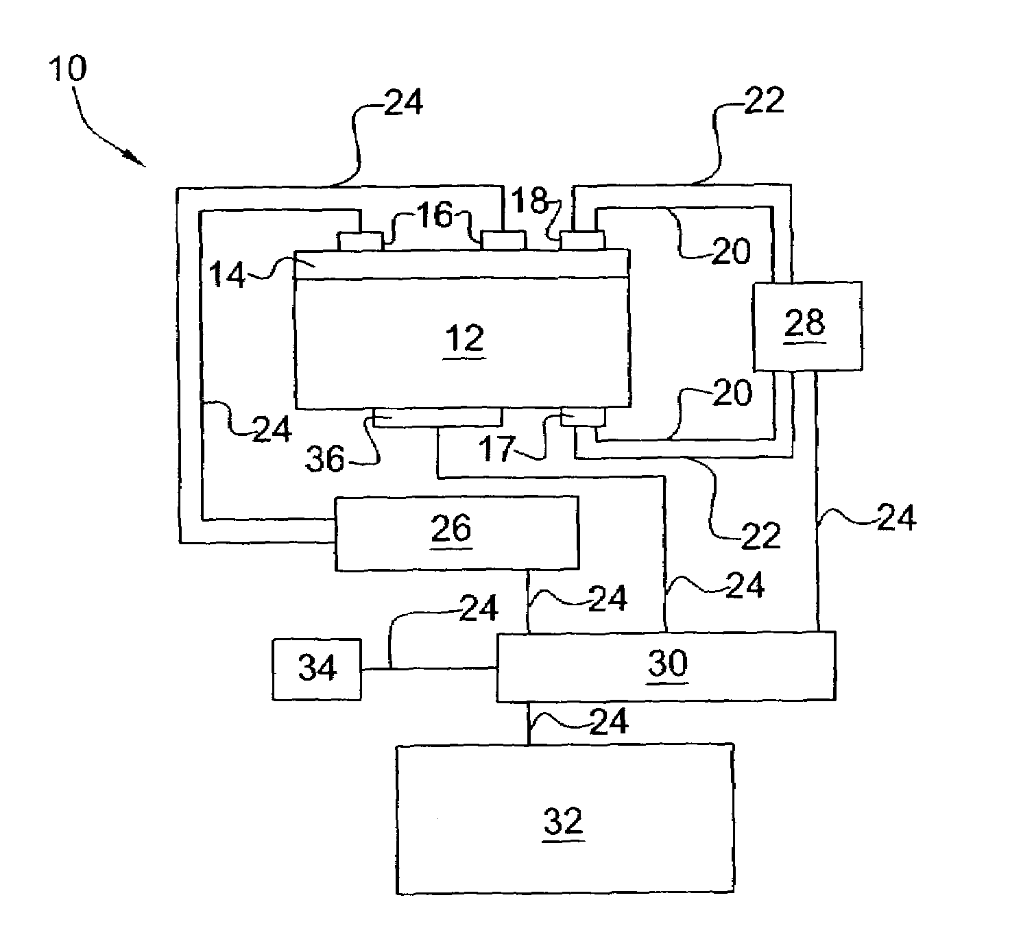
[0020]The present invention provides an in situ means for detecting the level of poisoning in a catalyst and means for maintaining precise control of the application of a DC electric field and, optionally, heat (temperature) thereto. Catalyzed reaction conditions can be optimized for maximum conversion of reactant chemical species and / or selection of certain reaction pathways and products. The DC current can be set to maximize the number of catalytically effective sites in the catalyst, if desired. The reaction temperature of the catalyzed reaction can be set to maximize reaction rate and / or select certain...


PUM

PropertyMeasurementUnit
temperatureaaaaaaaaaa
frequenciesaaaaaaaaaa

Abstract

The present invention provides methods and systems for controlling a catalytic process. The control system includes: an electroconductive support having a layer of a catalyst thereon; a first electrode in contact with said electroconductive support; a second electrode in contact with said catalyst layer; a current control unit for applying a current to said first and second electrodes and for controlling and varying the amount of current applied; an impedance measurement unit for continuously, monitoring and measuring the polarization impedance across an interface between the catalyst layer and the electroconductive support; a processing-unit for comparing the measured polarization impedance with a reference value. The amount of current applied to the catalyst layer and the electroconductive support via the first and second electrodes is varied to change the polarization impedance when the measured polarization impedance differs from the reference value.

Description

[0001]Priority of U.S. Provisional Patent Application Ser. Nos. 60 / 416,966, filed on Oct. 8, 2002 and 60 / 395,729 filed on Jul. 12, 2002 is claimed under 35 U.S.C. §119(e).BACKGROUND OF THE INVENTION[0002]1. Field of the Invention[0003]The present invention relates to a control system for catalytic processes. The present invention further relates to a control system for in processes for reforming hydrocarbon streams and for pollution remediation of exhaust streams.[0004]2. Description of the Prior Art[0005]Catalyst systems are employed extensively to reform light hydrocarbon streams, i.e. reduce methane and other light hydrocarbons to hydrogen, and to remediate exhaust streams, i.e. reduce / oxidize internal combustion exhaust to innocuous compounds.[0006]A problem encountered with catalyst systems is poisoning of the catalyst. One source of such poisoning is adsorption / infiltration of oxygen-containing species such as carbon monoxide. Carbon monoxide interferes with the catalysis mech...

Claims


Application Information

Patent Timeline
Patent Type & Authority Patents(United States)
IPC IPC(8): F01N3/00B01D53/86B01J19/00C01B3/38
CPCB01D53/8696B01D53/9495B01D53/965B01J19/0006C01B3/38B01D2255/1021B01D2255/1023B01D2255/40Y02E60/324B01D2257/502B01D2257/702C01B2203/1082C01B2203/16B01D2257/404Y02P20/52Y02E60/32
Inventor STANCOVSKI, VICTORSEETHARAMAN, SRIDHAR
Owner PAPPAS PETER D
Why Eureka
Try Eureka