Enhanced carbon dioxide adsorbent

a carbon dioxide and adsorbent technology, applied in the field of enhanced carbon dioxide adsorbent, can solve the problems of low system pressure drop requirements, large adsorbent particle size needed in current adsorbent canisters, and easy breathing

Active Publication Date: 2008-02-05
MICROPORE
View PDF10 Cites 38 Cited by
  • Summary
  • Abstract
  • Description
  • Claims
  • Application Information

AI Technical Summary

Problems solved by technology

Thus, one of the limitations of current adsorbent canisters is the relatively large adsorbent particle size necessary to obtain low pressure drops and, in turn, ease of breathing.
Additionally, powered or forced air systems typically have low system pressure drop requirements and as a result low adsorbent pressure drops are required.
However, decreasing granule size results in increased pressure drop.
Although water is needed for the reaction between LiOH and CO2, too much water vapor has been shown to be detrimental to the reaction.
Without a CO2 removal benefit, pre-hydration of granules only increases the weight of the adsorbent, which is not desirable.
These studies indicate that the pre-hydration of LiOH granules provides no benefit and may be even detrimental for CO2 removal and adsorbent weight.
In summary, although water is important for the CO2 removal reaction, Wang, Davis and others have shown that only water in vapor form is beneficial and too much water, even in vapor form, is detrimental to the reaction of LiOH and CO2.
Pre-hydration of the LiOH has been shown to be ineffective at best and detrimental at worst.
In closed systems, such as submarine CO2 removal systems, the heat generated can result in adsorbent exhaust temperatures as high as 160 degrees Fahrenheit.
This level of heat generation results in excessive breathing temperatures for closed systems, such as a rescue hood used by firefighters, is detrimental in most applications.
One technique for reducing adsorbent system exhaust temperature includes utilizing molecular sieves downstream of CO2 removal systems, but are problematic due to added weight, size, cost, and breathing resistance.

Method used


Image

  • Enhanced carbon dioxide adsorbent
  • Enhanced carbon dioxide adsorbent
  • Enhanced carbon dioxide adsorbent

Examples


example 1

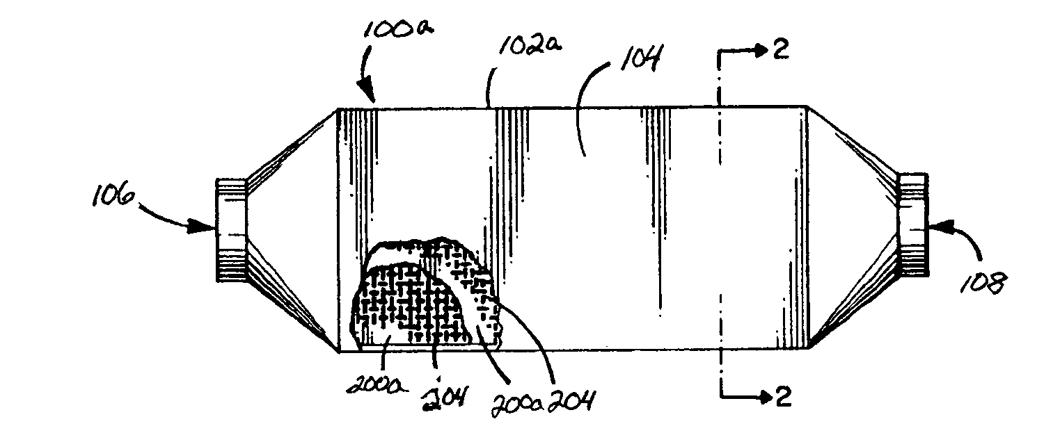
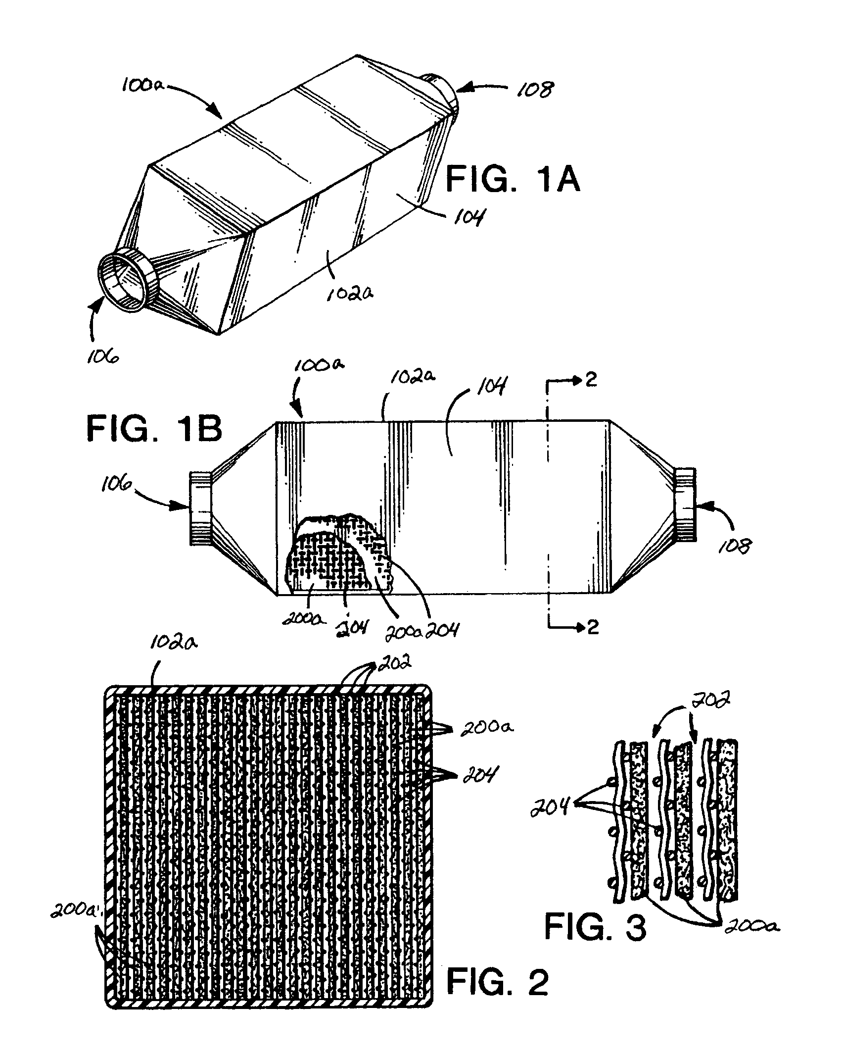
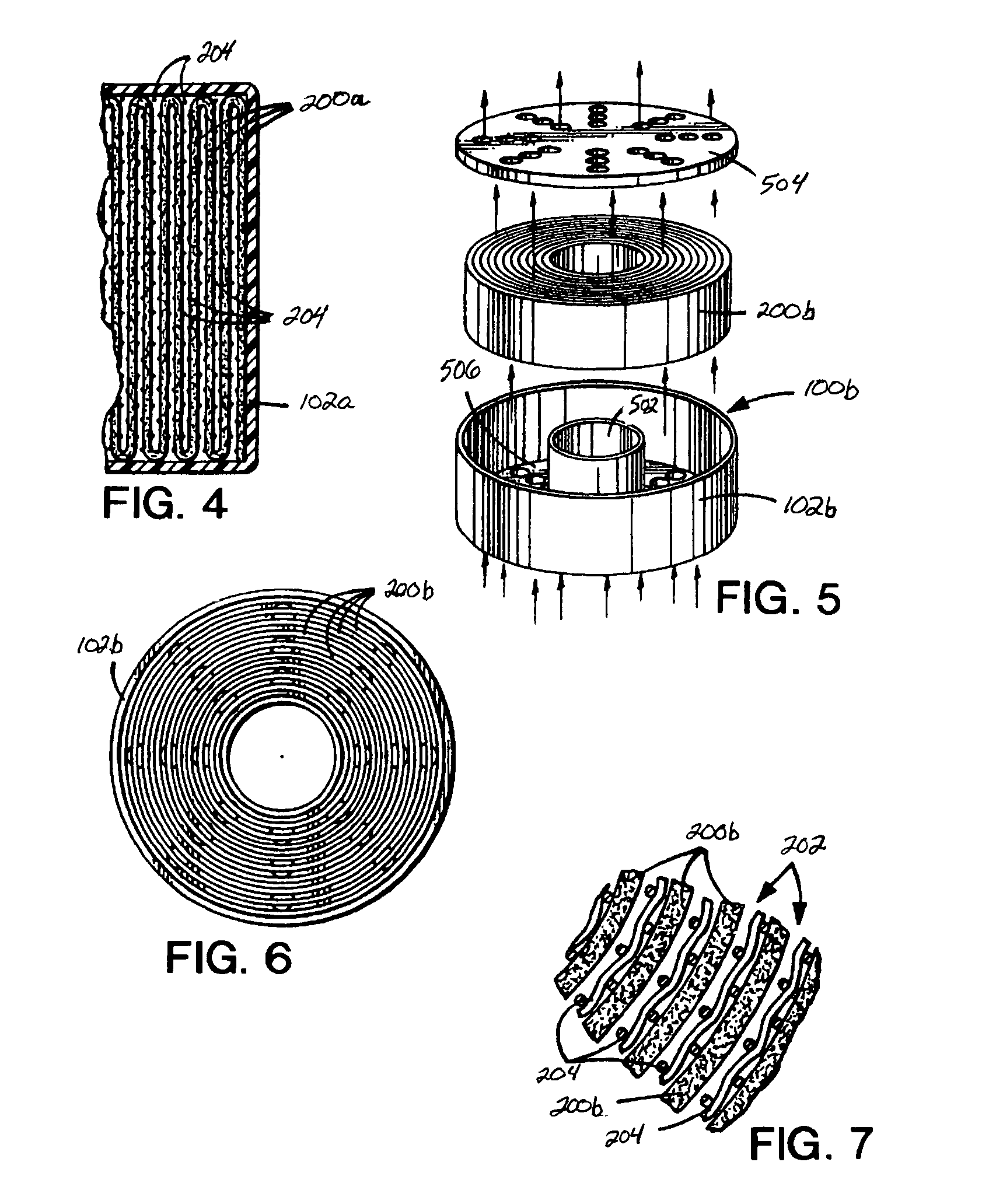
[0098]A pre-hydrated LiOH adsorbent sheet, wound into a cartridge may be made from the following components by spraying water onto the ribbed side of the sheet surface in order to achieve a 7% w / w water content:[0099]LiOH adsorbent density 0.71 g / cm3, 2.5 percent polyethylene, 0.025 inch rib height, 0.060 inch rib width, 0.120 inch channel width, 0.070 inch sheet thickness, density before water 134 g / ft2, cartridge length 12 inches, cartridge diameter 6½″, wound on a ½″ diameter polyethylene core with core plug.

example 2

[0100]LiOH CO2 cartridges may be made from the following components by spraying water onto the ribbed side of the sheet surface at the following levels: 0, 1.9, 4.7, 9 and 16.5 percent water weight / wet weight:[0101]LiOH adsorbent density between 0.59 and 0.66 g / cm3, 2.5 percent polyethylene, 0.032 inch rib height, 0.060 inch rib width, 0.120 inch channel width, 0.050 inch sheet thickness, density before water 94 g / ft2, cartridge length 2.5 inch, cartridge diameter 3 7 / 16 inches, wound on a ½ inch diameter polyethylene core with core plug.

[0102]The adsorbent LiOH density for Example 1 is 0.71 g / cm3. The LiOH adsorbent density for Example 2 is 0.59 to 0.66 g / cm3. The LiOH adsorbent density in sheet form for a U.S. Navy sub application is typically 0.81 g / cm3. The LiOH adsorbent density for CO2 adsorbent (sheet) according to the principles of the present invention may be controlled by the amount of oil used at the extrusion step. Removal of the oil at the extraction step results in voi...


PUM

PropertyMeasurementUnit
densityaaaaaaaaaa
diameteraaaaaaaaaa
diameteraaaaaaaaaa

Abstract

A CO2 removal system including a member having a first opening and a second opening to enable air flow containing carbon dioxide (CO2) to pass from the first opening to the second opening and lithium hydroxide (LiOH) supported by the member and having an initial water content above an anhydrous level. In one embodiment, LiOH adsorbent density is a maximum of approximately 1.0 g / cm3.

Description

CROSS-REFERENCES TO RELATED APPLICATIONS[0001]This application claims priority from U.S. Provisional Patent Application Ser. No. 60 / 539,343 filed Jan. 28, 2004, the entire teachings of which are herein incorporated by reference.BACKGROUND OF THE INVENTION[0002]A rebreather is a device that retains and reuses some or all of a user's expired breath. Even with physical exertion, a person uses only a fraction of the oxygen that is inhaled. A rebreather recirculates unused oxygen in the system and replenishes the oxygen consumed by the wearer. This allows a very small tank of oxygen to last much longer than is possible using traditional self contained breathing apparatus (SCBA) gear. Three main components of typical rebreather systems include a gas supply / oxygen control, counterlung, and carbon dioxide removal system.[0003]The carbon dioxide removal system maintains carbon dioxide CO2 (CO2) pressures at a safe level. Maintaining CO2 at safe pressure levels is relatively easy to do, and i...

Claims


Application Information

Patent Timeline
Patent Type & Authority Patents(United States)
IPC IPC(8): B01D53/02A61M16/22A62B19/00B01D53/04B01D53/14B01J20/04
CPCA61M16/22B01D53/02B01D53/025B01D53/0415B01J20/041B01J20/261B01J20/28033A62B19/00B01J2220/46B01D53/0431B01D53/0446B01D2251/302B01D2251/604B01D2253/10B01D2253/34B01D2257/504B01D2259/4533B01D2259/4541B01D2259/4575B01D2259/4583Y02C10/06Y02C10/08Y02C20/40
Inventor HRYCAK, MICHAEL B.MCKENNA, DOUGLAS B.
Owner MICROPORE
Why Eureka
Try Eureka