Ultrawideband antenna

a wideband antenna and ultra-wideband technology, applied in the field of wideband antennas, can solve the problems of insufficient broadband frequency response, causing time/phase dispersion, and relatively unsusceptible uwb communications systems to multi-path effects, and achieve the effect of improving the structure of electromagnetic antennas

Inactive Publication Date: 2008-02-05
INTEL CORP
View PDF43 Cites 27 Cited by
  • Summary
  • Abstract
  • Description
  • Claims
  • Application Information

AI Technical Summary

Benefits of technology

[0023]There is therefore a need for improved electromagnetic antenna structures, in particular for ultrawideband use.

Problems solved by technology

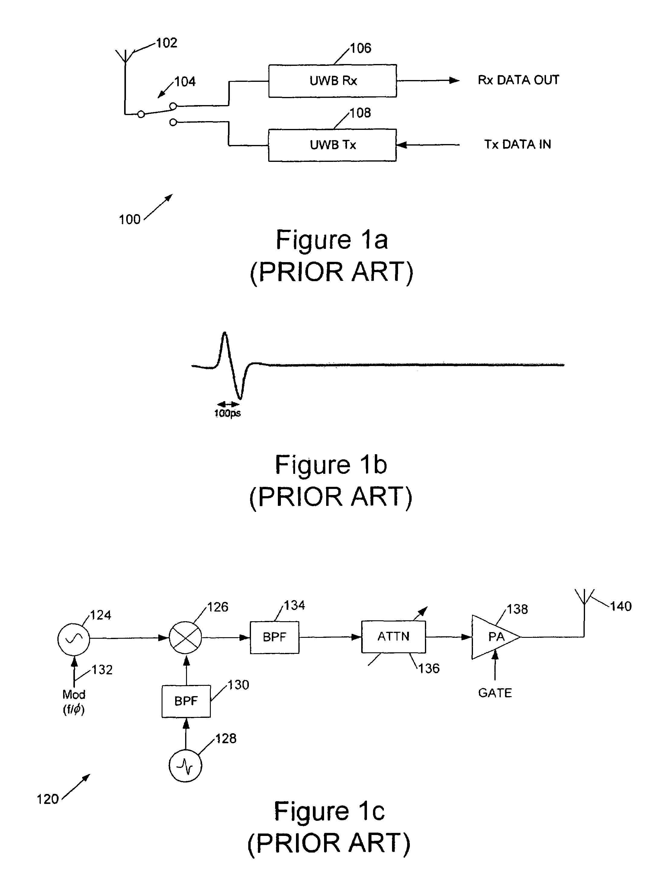
The short pulses also make UWB communications systems relatively unsusceptible to multipath effects since multiple reflections can in general be resolved.
However for many applications a broadband frequency response is not enough and a good phase response across the band is also required.
However because the dipole elements are spaced apart on the antenna, different frequency components reach the antenna at different times and thus the effective position of the antenna moves with frequency, giving rise to time / phase dispersion.
Biconical antennas can, however, have difficulties providing a sufficiently flat, wideband response and the biconical shape is relatively bulky, complex and expensive to manufacture.
Tapered slot or Vivaldi antennas have a theoretically infinite bandwidth but in practice there are difficulties providing a suitable feed to such an antenna.
The antennas can also be relatively costly to manufacture.
Again, however, this is a relatively complex configuration and the dipole shape appears to be based upon the principle of spreading the resonance of the antenna by, in effect, reducing the Q, but nonetheless the design would appear to exhibit significant potential for undesired resonances.
An elliptical planar dipole UWB antenna is described in US 2003 / 0090436 but the elliptical shape is non-optimal and the antenna apparently works by establishing current flows around the periphery of the antenna.
Circular patch antennas are known but these are relatively narrowband devices (their bandwidth does not approach that desirable in a UWB system) comprising a circular area of copper parallel to a ground plane.

Method used


Image

  • Ultrawideband antenna
  • Ultrawideband antenna
  • Ultrawideband antenna

Examples


Embodiment Construction

[0082]Referring now to FIG. 2a, this shows, diagrammatically, a set of quarter wave resonant elements 200a-200h together with their respective frequency responses 202a-202h. As can be seen the frequency responses overlap to, in theory, provide a substantially flat response over a wide bandwidth. FIG. 2b illustrates how these resonant elements may be combined in practice, using a common feed point 204. However, the arrangement of FIG. 2b has angular response and polarisation which is a function of frequency, and this is addressed by combining two sets of elements in a symmetric structure 210 as shown in FIG. 2c.

[0083]The way in which the structure of FIG. 2c works can be explained with reference to FIG. 2d, which shows a pair of current of equal magnitude which sum to give a resultant vector along line 214 bisecting the angle between vectors 212a and 212b. In the structure of FIG. 2c each element apart from the central element 202 is paired, elements of a pair lying at equal angles ...


PUM


Abstract

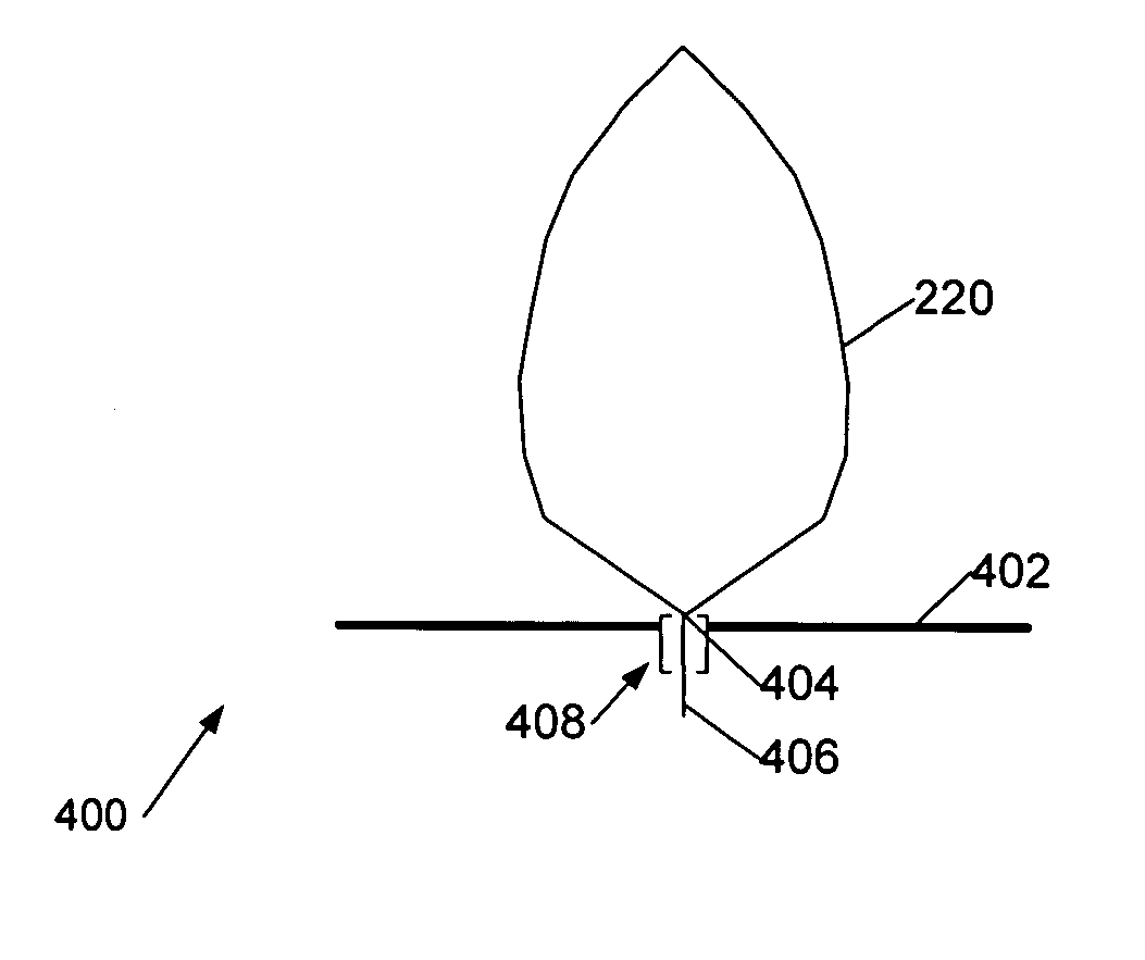
Antennas for transmitting and receiving ultrawideband (UWB) signals are disclosed. A UWB antenna structure includes a planar conductor of substantially uniform resistance. The structure has the shape of a pair of conjoined, generally triangular figures, each with a long side, a short side, and a curved side. The triangular figures have an antenna feed connection at one corner. The structure has an axis of symmetry passing through the antenna feed connection.

Description

[0001]This application is a continuation-in-part of PCT / GB2003 / 05070 and hereby claims the benefit of the filing date of Nov. 21, 2003 and is incorporated by reference herein.BACKGROUND OF THE INVENTION[0002]This invention generally relates to wideband antennas, and in particular to antennas for transmitting and receiving ultrawideband (UWB) signals.[0003]Techniques for UWB communication developed from radar and other military applications, and pioneering work was carried out by Dr G. F. Ross, as described in U.S. Pat. No. 3,728,632. Ultra-wideband communications systems employ very short pulses of electromagnetic radiation (impulses) with short rise and fall times, resulting in a spectrum with a very wide bandwidth. Some systems employ direct excitation of an antenna with such a pulse which then radiates with its characteristic impulse or step response (depending upon the excitation). Such systems are referred to as carrierless or “carrier free” since the resulting rf emission lack...

Claims


Application Information

Patent Timeline
Patent Type & Authority Patents(United States)
IPC IPC(8): H01Q1/38H01Q1/48H01Q5/00H01Q5/15H01Q5/25H01Q9/28H01Q21/30
CPCH01Q5/00H01Q9/28H01Q5/25H01Q9/40H01Q21/30H01Q9/285
Inventor STARKIE, TIMOTHY JOHN STEFANSMITH, LESLIE DAVID
Owner INTEL CORP
Why Eureka
Try Eureka