Cancer detection and adaptive dose optimization treatment system

a treatment system and cancer technology, applied in the field of cancer detection and precancer treatment systems, can solve the problems of two-part problem, difficult detection of emitted light, and discrimination between light emitted from normal cells and light emitted from cancerous or precancer cells, and achieve the effect of improving patient comfort, cost containment and health outcomes

Inactive Publication Date: 2008-02-05
FOSTER-MILLER
View PDF33 Cites 33 Cited by
  • Summary
  • Abstract
  • Description
  • Claims
  • Application Information

AI Technical Summary

Benefits of technology

[0014]The present invention improves patient comfort, cost containment and health outcomes by integrating the detection and treatment phases. The treatment light source is spatially-modulated (or beam-shaped) so that only the areas of tissue that are found to be cancerous or pre-cancerous (using the detection method described above) are illuminated with the activation light. The amount of illumination (and its spatial composition) is continuously adapted throughout the treatment. In addition, the treatment and detection systems of this invention are coupled, so that as any cancerous and / or pre-cancerous area is being treated by the treatment system, the area is (either simultaneously or alternately) being detected by the detection system to update not only the boundaries of the diseased region, but the entire area illuminated. As the cancerous or pre-cancerous cells die off, or as the photo-activating agent “bleaches” (non-linearly), the region of tissue that requires illumination will diminish and change shape. This diminishing and shape-changing will be detected by the detection system in real-time or near-real-time, and the shape of the beam and its intensity of activation light will automatically be changed accordingly, so that only the cancerous or pre-cancerous region is being illuminated with activation light and in proportion to the amount of disease.

Problems solved by technology

Thus, the detection of emitted light, and especially the discrimination between light emitted from normal cells and that emitted from cancerous or pre-cancerous cells, becomes a difficult, two-part problem to solve.
The method presented in U.S. Pat. No. 6,208,749 does not obtain images simultaneously and does not provide a method for treatment of pre-cancer or cancerous cells.
Again, these methods do not provide a means of treatment for pre-cancer or cancerous cells.
The method of U.S. Pat. No. 6,135,965 is non-imaging, is not coaxial and does not provide a means for treatment of pre-cancer or cancerous cells.
The method in U.S. Pat. No. 5,623,932 for detection is non-imaging and further does not provide a means for treatment of pre-cancer or cancerous cells.
U.S. Pat. No. 5,514,127 requires the use of an endoscope and additionally does not provide treatment simultaneously with detection.

Method used


Image

  • Cancer detection and adaptive dose optimization treatment system
  • Cancer detection and adaptive dose optimization treatment system
  • Cancer detection and adaptive dose optimization treatment system

Examples


first embodiment

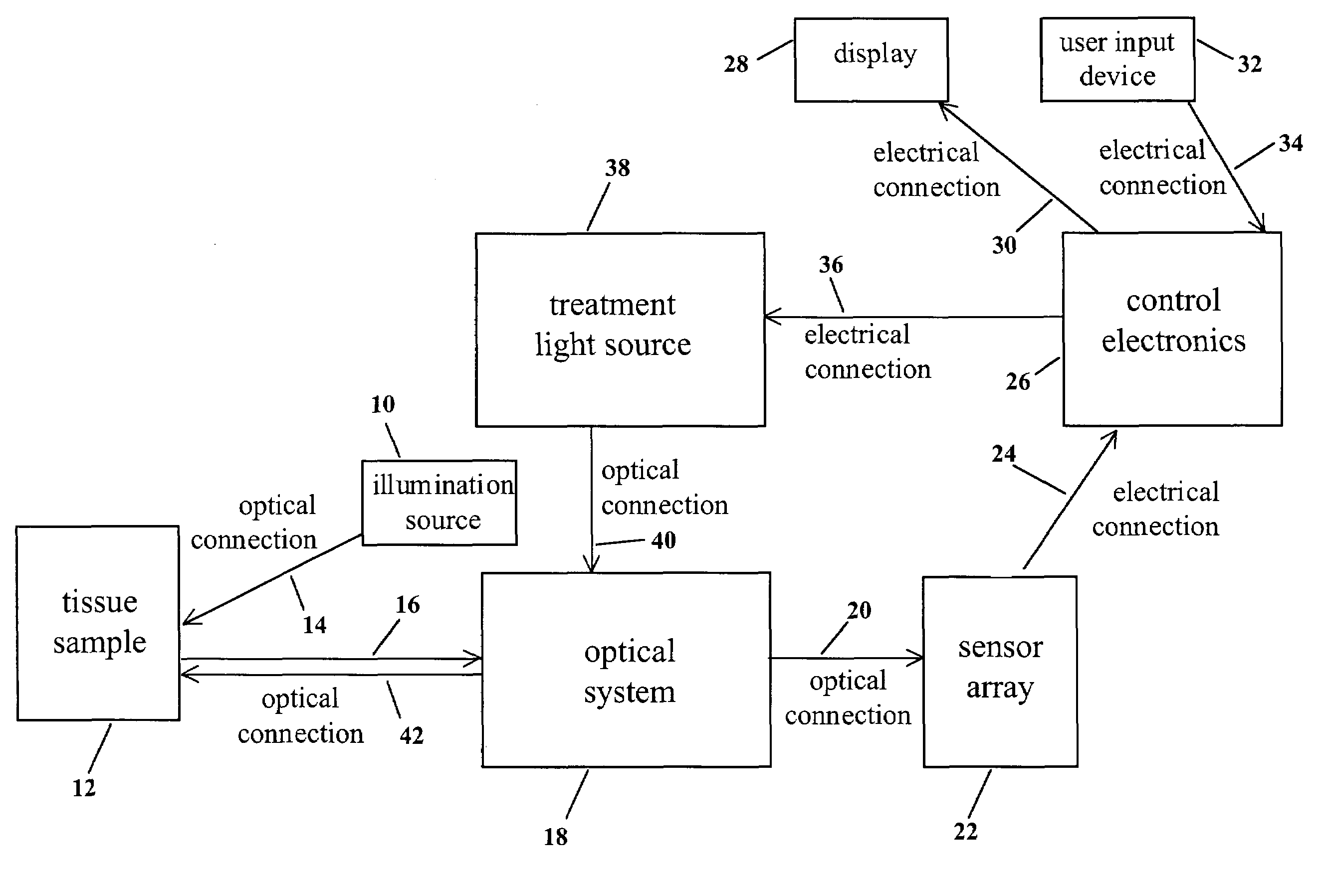
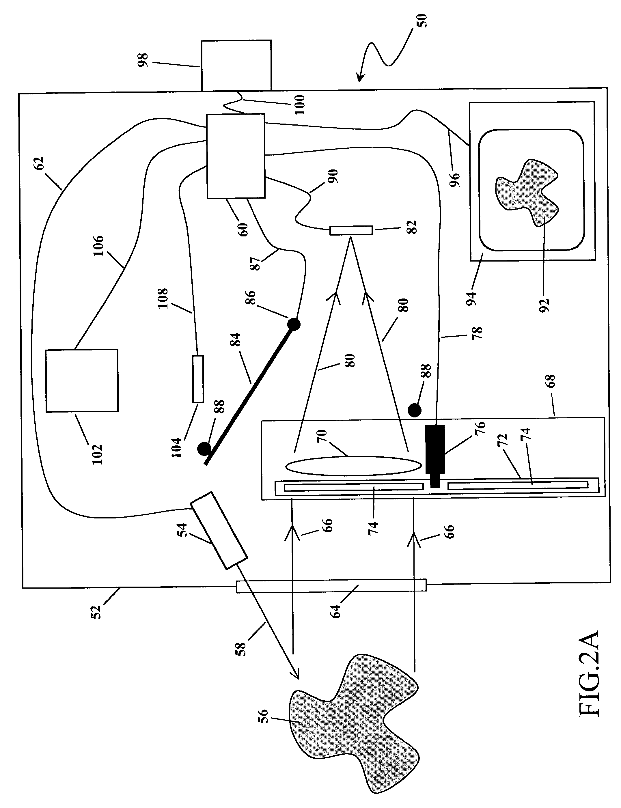
[0029]The action of this first embodiment of the invention 50 is separated in two distinct phases. The first phase of the action is depicted in FIG. 2A and the second phase of the action is depicted in FIG. 2B.

[0030]As shown in FIG. 2A and FIG. 2B, all the components of this embodiment of the invention 50 are enclosed within and / or attached to a housing 52. Referring to FIG. 2A, in the first phase of the action, an illumination source 54 is used to illuminate a target tissue sample 56 with optical radiation 58. The illumination source 54 may emit optical radiation 58 of any range of wavelengths. For example, the illumination source 54 may emit ultraviolet radiation 58 in the range 340-380 nm. Or the illumination source 54 may emit white light 58 in the range 400-700 nm. Or the illumination source 54 may emit infrared radiation 58 in the range 600-900 nm. Or the illumination source 54 may emit a combination of ultraviolet, visible, and / or infrared illumination 58. Furthermore, the va...

second embodiment

[0043]In this second embodiment, the multiple imaging optical system 218 comprises a plurality of imaging lens elements 220, a set of filters arranged in a plane 222, and a beam-splitting pyramid prism 224. The exact construction and action of the multiple imaging optical system 218 may, preferably, be as described below.

[0044]The multiple imaging optical system uses a series of optical elements to produce multiple simultaneous adjoining images on a single image plane. A first, intermediate, image is produced using the first telecentric imaging lens. This intermediate image is produced at a plane coincident with an adjustable-size rectangular field stop. The rectangular field stop is mounted in a sub-housing that allows its free rotation. A second telecentric lens collimates the light from the intermediate image. This collimated light is next passed through an optical splitting means, which uses the principal of refraction to separate the light into multiple components. The optical ...

third embodiment

[0051]FIG. 6 shows a schematic illustration of a third preferred embodiment of the invention 300. As shown in FIG. 6, all the components of this embodiment of the invention 300 are enclosed within and / or attached to a housing 302. This third embodiment acts in two separate and distinct phases, which two phases are herein called detection phase and treatment phase. In the normal course of action, the detection phase of action is performed prior to the treatment phase.

[0052]In the detection phase of action, an illumination source 304 is used to illuminate a target tissue sample 306 with optical radiation 308. The illumination source 304 may emit optical radiation 308 of any range of wavelengths. For example, the illumination source 304 may emit ultraviolet radiation 308 in the range 340-380 nm. Alternatively, the illumination source 304 may emit white light 308 in the range 400-700 nm. The illumination source 304 may also emit infrared radiation 308 in the range 600-900 nm. Or alterna...


PUM


Abstract

The present invention utilizes a series of optical and electronic elements to detect and image cancerous and / or pre-cancerous cells in living tissue. The invention further uses the images thus obtained to adaptively and dynamically shape a treatment light beam so as to maximize the beam's intensity in proportion to the areas with the most cancer or pre-cancer and to minimize the irradiation of normal tissue by the beam.

Description

CROSS REFERENCE TO RELATED APPLICATIONS[0001]This application claims priority of U.S. Provisional Application 60 / 356,302 filed on Feb. 12, 2002, which is incorporated by reference herein, and of U.S. Provisional Application 60 / 363,997 filed on Mar. 14, 2002, also incorporated by reference herein.BACKGROUND[0002]This invention relates to detection and treatment systems for cancer and pre-cancer, and more specifically to a detection and treatment system that first detects cancerous and pre-cancerous tissue in situ, and then dynamically and automatically shapes and re-shapes its photodynamic therapy (PDT) treatment beam during the course of treatment to maximize the effect of the treatment beam while simultaneously minimizing the illumination of surrounding normal tissue.[0003]Analyzing living cells using fluorescence of a dye, which is produced in an interaction between tissue and an injected chemical, is a well-understood method in the field of medical science. In this method of anal...

Claims


Application Information

Patent Timeline
Patent Type & Authority Patents(United States)
IPC IPC(8): A61B6/00A61B5/00A61B17/00A61B18/20A61N5/06
CPCA61B5/0059A61N5/062A61B18/20A61B2017/00057A61B2018/00636
Inventor MOORADIAN, GREGORY C.SAGGESE, STEVENTOCCI, MICHAEL D.TOCCI, NORA C.
Owner FOSTER-MILLER
Why Eureka
Try Eureka