Valve timing control system and control system for an internal combustion engine

a timing control system and internal combustion engine technology, applied in valve drives, combustion air/fuel air treatment, machines/engines, etc., can solve the problems of increased exhaust emissions, degraded fuel economy, and reduced fuel economy, and achieve excellent combustion performance and reduce exhaust emissions

Inactive Publication Date: 2008-02-19
HONDA MOTOR CO LTD
View PDF8 Cites 31 Cited by
  • Summary
  • Abstract
  • Description
  • Claims
  • Application Information

AI Technical Summary

Benefits of technology

[0011]It is a first object of the present invention to provide a valve timing control system, which is capable of controlling the amount of

Problems solved by technology

The switching of the valve-closing timing is performed for the following reason: The amount of air to be drawn into the cylinder is smaller in the low-load region of the engine than in the high-load region of the same, and if the amount of intake air is reduced by reducing the degree of opening of a throttle valve, pumping loss occurs due to the lowering of pressure (increase in negative pressure) within the intake valve, resulting in degraded fuel economy.
Therefore, this system is incapable of controlling the amount of intake air in an accurate and fine-grained manner, so that the amount of intake air may become short

Method used


Image

  • Valve timing control system and control system for an internal combustion engine
  • Valve timing control system and control system for an internal combustion engine
  • Valve timing control system and control system for an internal combustion engine

Examples


Embodiment Construction

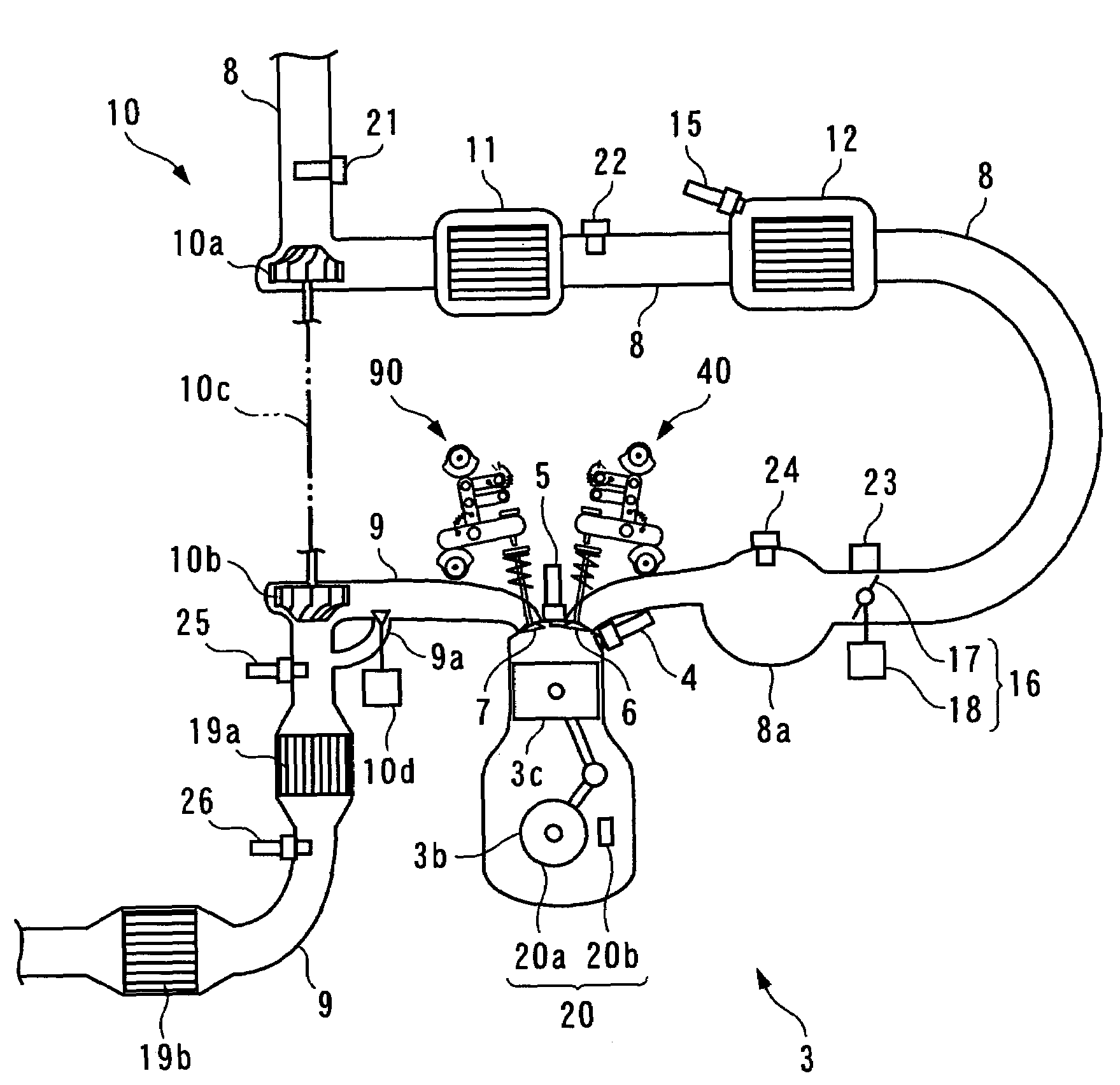
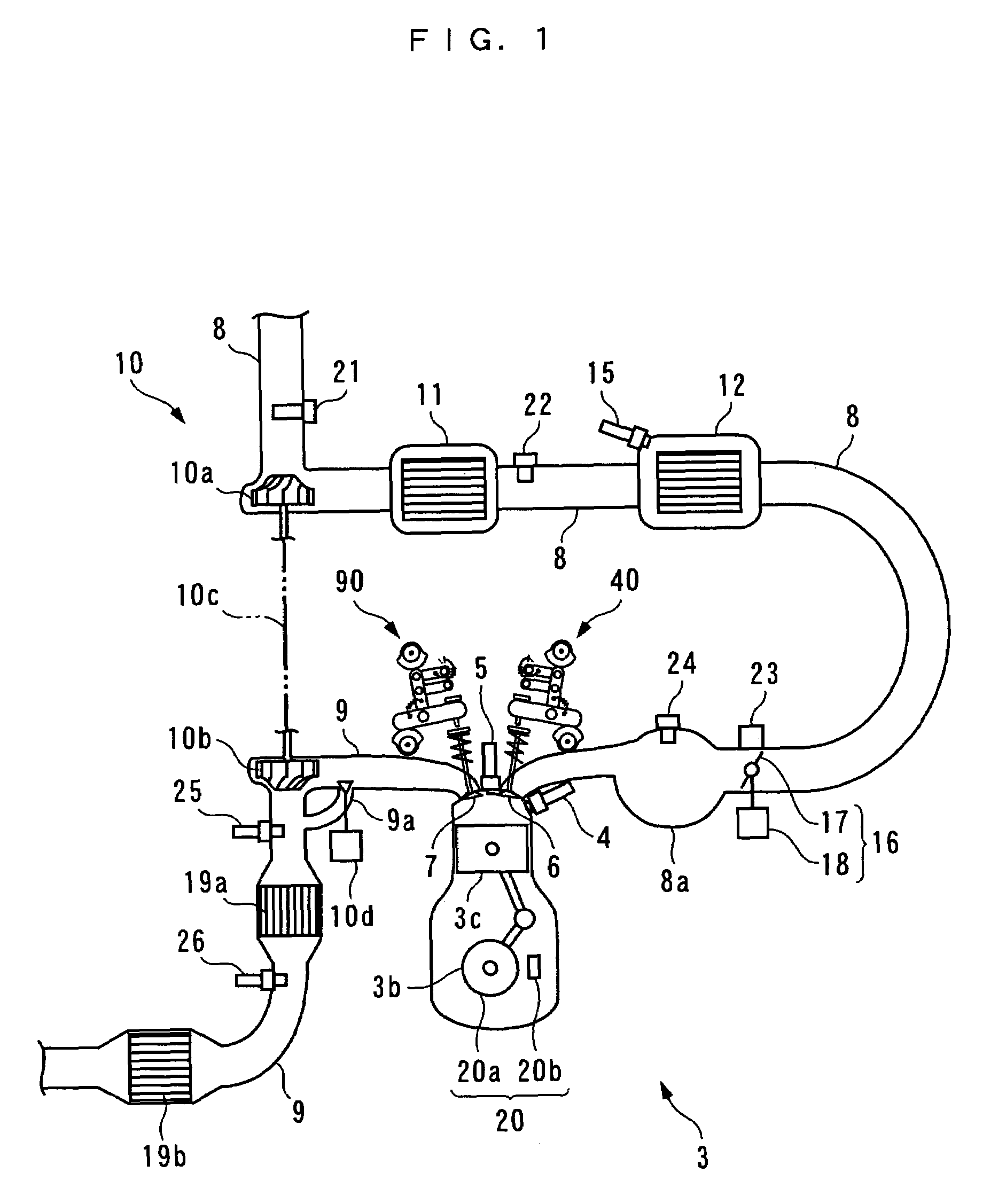
[0115]The invention will now be described in detail with reference to the drawings showing a preferred embodiment thereof. Referring first to FIGS. 1 and 2, there is schematically shown the arrangement of an internal combustion engine 3 (hereinafter simply referred to as “the engine 3”) to which is applied a valve timing control system / control system 1 for an internal combustion engine (hereinafter referred to “the control system 1”), according to the present embodiment. FIG. 3 schematically shows the arrangement of the control system 1. As shown in FIG. 3, the control system 1 includes an ECU 2. The ECU 2 carries out control processes, as described hereinafter, including a process for control of valve timing of intake valves 6 and a boost pressure control process, based on operating conditions of the engine 3.

[0116]The engine 3 is an inline four-cylinder gasoline engine installed on an automotive vehicle, not shown, and has first to fourth cylinders #1 to #4 (see FIG. 5). Further, ...


PUM


Abstract

A valve timing control system for an internal combustion engine, which is capable of accurately and delicately controlling an amount of intake air, and thereby maintaining excellent combustion state and reduced exhaust emissions. The valve timing control system variably controls the valve-closing timing of an intake valve with respect to valve-opening timing of the same as desired via a variable intake valve actuation assembly. The ECU of the engine determined a basic value of a target auxiliary intake cam phase according to the demanded drive torque of the engine. The ECU calculates a control input to the variable intake valve actuation assembly such that the cylinder intake air amount converges to a target intake air amount and at the same time the auxiliary intake cam phase is constrained to the basic value of the target auxiliary intake cam phase.

Description

BACKGROUND OF THE INVENTION[0001]1. Field of the Invention[0002]The present invention relates to a valve timing control system for an internal combustion engine, for controlling valve timing of intake valves of the engine, and a control system for an internal combustion engine, for controlling boost pressure of intake air via a supercharging device and variably controlling valve-closing timing of intake valves with respect to valve-opening timing thereof as desired via a variable valve timing device.[0003]2. Description of the Related Art[0004]Conventionally, a valve timing control system for an internal combustion engine, for controlling valve timing of intake valves of the engine has been proposed e.g. in Japanese Laid-Open Utility Model Registration Publication (Kokoku) No. S56-9045 (pages 1 and 2, FIGS. 1 to 4). This engine includes a rocker arm for opening and closing each intake valve, and two cams, one for low load (low-load cam) and the other for high load (high-load cam), p...

Claims


Application Information

Patent Timeline
IPC IPC(8): F01L1/34F01L1/08F01L1/18F01L1/20F01L1/344F01L1/46F01L13/00F01N13/00F02B29/04F02B37/18F02D13/02F02M31/20
CPCF01L1/022F01N13/009F01L1/18F01L1/182F01L1/20F01L1/3442F01L1/462F01L13/0047F02B29/0412F02D13/0207F02D13/0238F02D13/0269F02M31/20F01N13/0093F01L1/08F01L2001/0537F01L2001/3443F01L2105/00F01L2800/00F01L2820/02F02B37/18Y02T10/146Y02T10/126Y02T10/142F01L2305/00Y02T10/12
Inventor YASUI, YUJIYONEKAWA, AKIYUKI
Owner HONDA MOTOR CO LTD
Why Eureka
Try Eureka