System and method for purging fuel vapors using exhaust gas

a technology of exhaust gas and fuel vapor, which is applied in the direction of liquid fuel feeders, combustion air/fuel air treatment, machines/engines, etc., can solve the problems of increased engine pumping work, increased parasitic losses, and loss of fuel savings, so as to facilitate certain emission control activities and reduce the emission of such vapors

Active Publication Date: 2008-02-19
FORD GLOBAL TECH LLC
View PDF14 Cites 36 Cited by
  • Summary
  • Abstract
  • Description
  • Claims
  • Application Information

AI Technical Summary

Benefits of technology

[0001]Vehicles having internal combustion engines typically utilize intake manifold vacuum for power accessories and facilitating certain emission control activities. In particular, engines utilize intake manifold vacuum to draw stored fuel vapors from a carbon canister or other vapor storage device. In this way, fuel vapors generated in the fuel tank can be contained and then used in the engine to reduce emission of such vapors.
[0003]However, the inventors herein have recognized several issues with such approaches. While adjusting engine operation may be appropriate under some conditions, it may also result in lost fuel savings due to an inability to operating in a more efficient combustion mode. For example, due to a need to purge fuel vapors, the engine may operate in more efficient combustion modes, such as HCCI, less often than otherwise possible. Also, throttling to generate vacuum may increase engine pumping work. Further, utilizing external vacuum pumps or other such devices can also increase parasitic losses and thus degrade fuel economy, in addition to increasing cost.
[0004]The inventors herein have further recognized that it may be beneficial to push the vapors from the canister into the intake manifold using exhaust pressure, rather than, or in addition to, pulling the vapors using manifold vacuum. In this way, it may be possible to enable additional operation at lower vacuum levels, thus extending more fuel efficient combustion modes, for example.
[0005]Further, increased temperature from the exhaust gas may enable more efficient purging under some conditions. Specifically, the higher temperature of the exhaust gas (compared with fresh air) may help purge fuel vapors from a vapor storage device, such as a charcoal canister since vapor purging is an endothermic reaction. In other words, the charcoal canister normally cools when fresh air is used for purging. Using at least some exhaust gas for purging would raise the temperature and thus enable purging with a smaller volume of gas, further reducing the need for intake manifold vacuum.

Problems solved by technology

However, the inventors herein have recognized several issues with such approaches.
While adjusting engine operation may be appropriate under some conditions, it may also result in lost fuel savings due to an inability to operating in a more efficient combustion mode.
For example, due to a need to purge fuel vapors, the engine may operate in more efficient combustion modes, such as HCCI, less often than otherwise possible.
Also, throttling to generate vacuum may increase engine pumping work.
Further, utilizing external vacuum pumps or other such devices can also increase parasitic losses and thus degrade fuel economy, in addition to increasing cost.

Method used


Image

  • System and method for purging fuel vapors using exhaust gas
  • System and method for purging fuel vapors using exhaust gas
  • System and method for purging fuel vapors using exhaust gas

Examples


Embodiment Construction

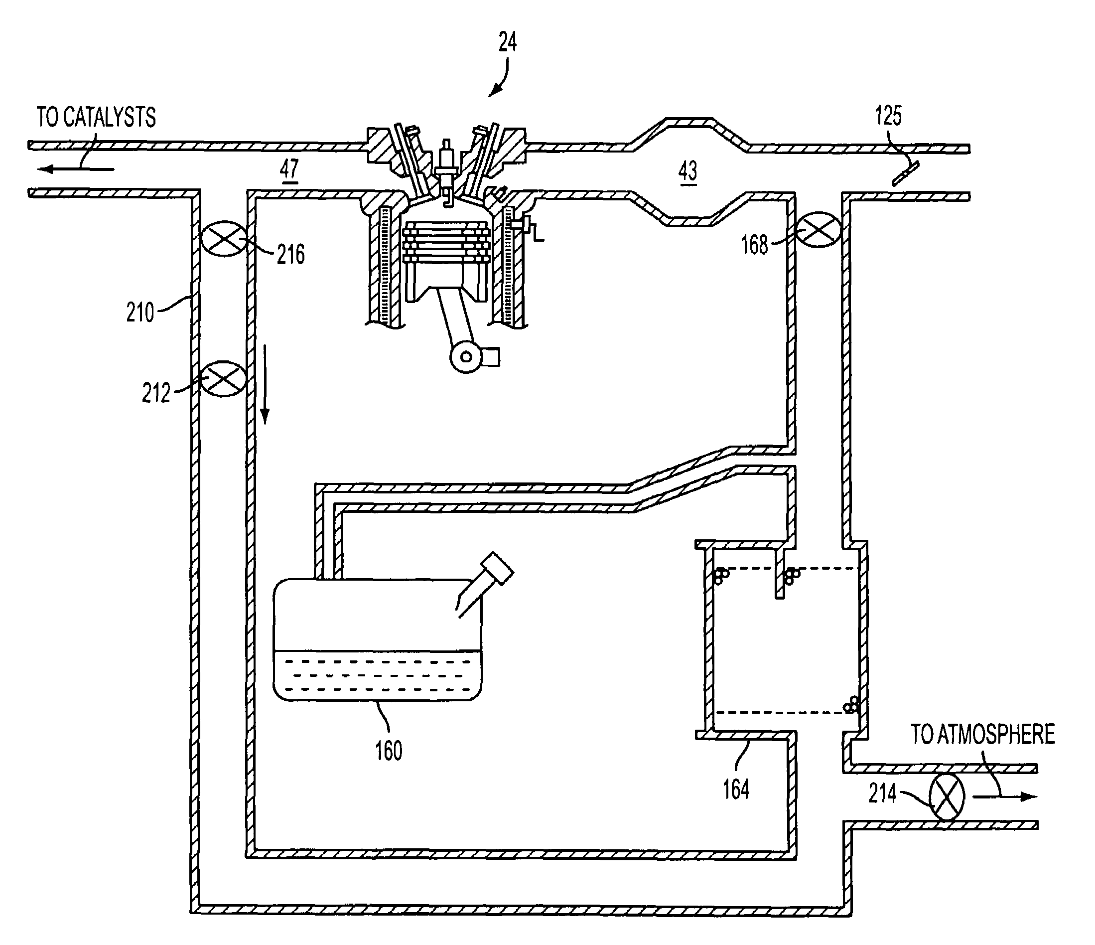
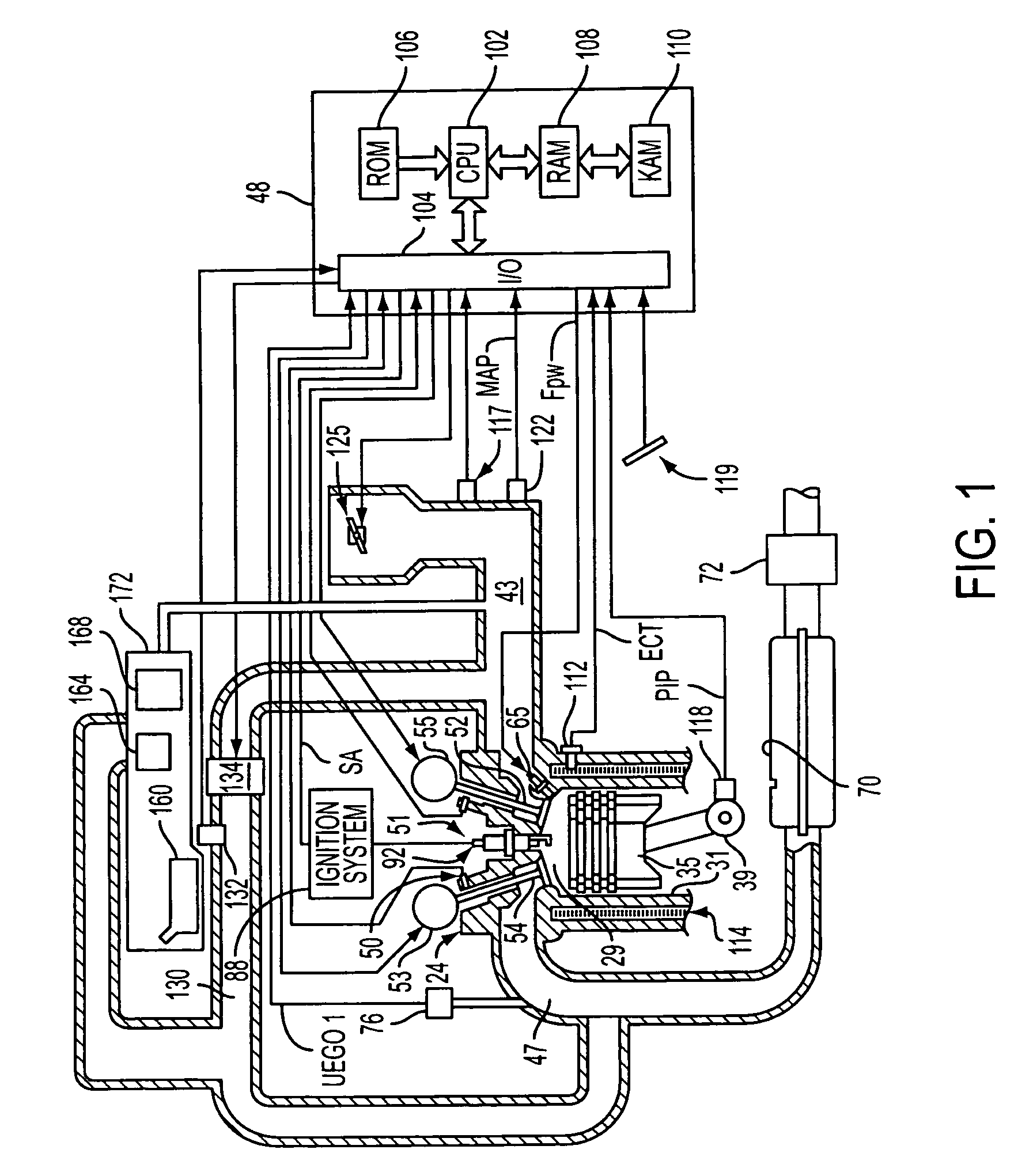
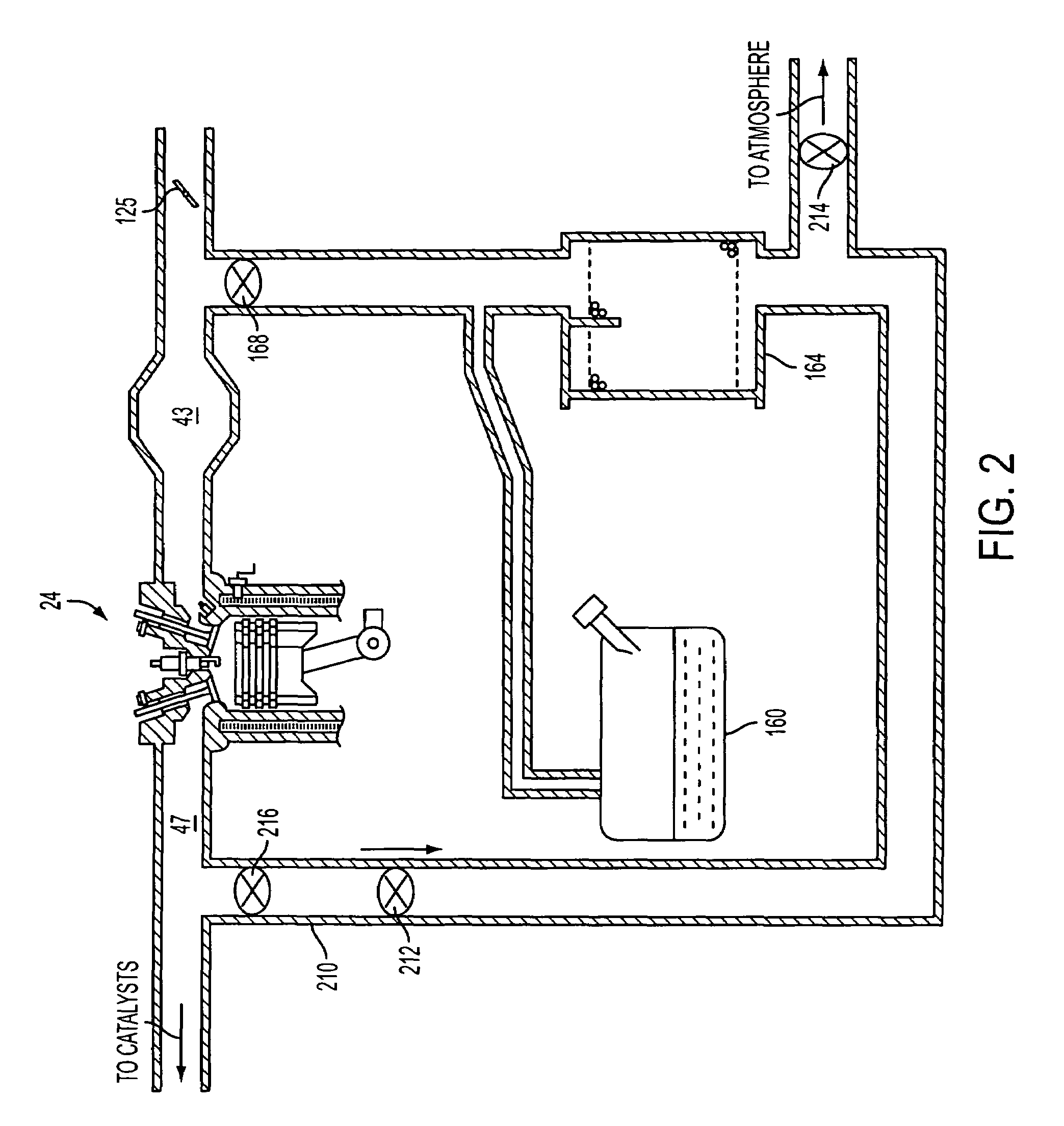
[0010]FIG. 1 shows an example engine 24 as a direct injection gasoline engine with a spark plug; however, engine 24 may be a port injection gasoline engine, or a diesel engine without a spark plug, or another type of engine. Internal combustion engine 24 may include a plurality of cylinders, one cylinder of which is shown in FIG. 1, which is controlled by electronic engine controller 48. Engine 24 includes combustion chamber 29 and cylinder walls 31 with piston 35 positioned therein and connected to crankshaft 39. Combustion chamber 29 is shown communicating with intake manifold 43 and exhaust manifold 47 via respective intake valve 52 and exhaust valve 54. While only one intake and one exhaust valve are shown, the engine may be configured with a plurality of intake and / or exhaust valves.

[0011]Engine 24 is further shown configured with an exhaust gas recirculation (EGR) system configured to supply exhaust gas to intake manifold 43 from exhaust manifold 47 via EGR passage 130. The am...


PUM


Abstract

A system for a vehicle, comprising of an engine, and a fuel vapor storage system coupled to the engine configured to store and release fuel vapors, the system further configured to route exhaust gas from the engine to the vapor storage system and where adsorbed vapors are released into the exhaust gas before the exhaust gas is re-inducted into the engine to be burned.

Description

BACKGROUND AND SUMMARY[0001]Vehicles having internal combustion engines typically utilize intake manifold vacuum for power accessories and facilitating certain emission control activities. In particular, engines utilize intake manifold vacuum to draw stored fuel vapors from a carbon canister or other vapor storage device. In this way, fuel vapors generated in the fuel tank can be contained and then used in the engine to reduce emission of such vapors.[0002]Various types of engine operation can affect the level of vacuum in the intake manifold, such as variation in the engine load, engine air-fuel ratio, engine valve timing and / or lift, cylinder deactivation, and engine combustion mode (such as homogenous charge compression ignition operation, HCCI), for example. Under some conditions, such engine operation can reduce available vacuum below that needed to purge sufficient fuel vapors. Thus, some approaches adjust engine operation (e.g., by adjusting air-fuel ratio, valve timing, thro...

Claims


Application Information

Patent Timeline
Patent Type & Authority Patents(United States)
IPC IPC(8): F02M37/20F01N3/00
CPCF02M25/074F02M25/0742F02M25/08F02B1/12F02M25/0754F02M25/0755Y02T10/121F02M26/35F02M26/36F02M26/46F02M26/47
Inventor LEONE, THOMASCUNNINGHAM, RALPH WAYNE
Owner FORD GLOBAL TECH LLC
Why Eureka
Try Eureka