Method and apparatus for fluorescent confocal microscopy

a fluorescent confocal microscope and fluorescent confocal technology, applied in the field of methods and apparatus for fluorescent confocal microscopes, can solve the problems of reducing the ability, unsatisfactory background fluorescence, signal noise, etc., and achieve the effect of improving the confocal fluorescence microscop

Active Publication Date: 2008-02-26
LEICA MICROSYSTEMS CMS GMBH
View PDF14 Cites 110 Cited by
  • Summary
  • Abstract
  • Description
  • Claims
  • Application Information

AI Technical Summary

Benefits of technology

[0013]The instant invention presents a new and improved confocal fluorescence microscope. The new microscope has significant advantages relative to existing implementations of microscope confocal imagers. In common with previous confocal imagers the instant invention has the advantages relative to conventional wide-field and confocal fluorescence imagers. However, the instant invention also addresses the drawbacks of confocal technology in terms of cost and complexity, and provides significant savings in both due to the simplicity of the components and the elimination of the need, for example, of the physical spatial filters such as pinholes or slits. The system is also compatible with a wide range of micro well plates including thin-bottom 96, 386, and 1536-well plates, microscope slides, and can support for a wide range of fluorescent dyes.
[0014]The system comprises at least one, or more preferably two or more optical sources (preferably lasers) which will operate at different excitation wavelengths aligned with corresponding fluorescent or fluorescently stained or labelled targets. The fluorescent emission from each target is filtered using bandpass optical filters and the emission data is collected by at least one imaging device, preferably two or more imaging devices. The system presents certain distinct advantages over the prior wide-field fluorescence microscopes described above, including improved image quality and increased sensitivity. More specifically, in ordinary fluorescence microscopy, emission from the material above and below the focal plane fluoresces results in undesirable background fluorescence. Conventional wide-field fluorescence microscopes do not provide effective suppression of this background and, consequently, such microscopes will produce a relatively small signal from the target cellular material which “rides-on-top” of, and is affected by, a larger background signal. For example, when a microtiter plate with a biological sample is imaged by a wide field fluorescence microscope, background from the clear plastic bottom of the well-plate and the media above the cellular material will ordinarily be substantially greater than the signal of cellular material. Analysis of such images is routinely accomplished by estimating and then subtracting this background.
[0016]1. The statistical noise in the signal of interest is increased as a result of the background. This reduces the ability to identify features of interest because such background fluorescence is typically responsible for >90% of the noise in the image and must be corrected for by estimating the contribution of the background noise. Further, because this estimation involves certain assumptions, this complicates analysis and interpretation and it decreases the sensitivity of the system.
[0018]The use of a confocal imaging microscope will typically suppress this background fluorescence by a factor of 20 to 100 relative to the fluorescence signal from the focal plane, thereby permitting a more accurate image to be obtained. However, confocal microscopes are often costly and complex to operate and use. The instant system reduces the cost and complexity of the system by introducing a simplified detection sub-system comprising one or more detector capable of random access for detecting the fluorescent emission. The detector is preferably a low cost, CMOS optical sensor which minimizes the contribution due to the dark current to negligible, even when the sensor is operated at room temperature, however other pixel-based detectors, such as appropriate CCD cameras can also be used. Suitable detection devices are described in CMOS Imagers: From Phototransduction to Image Processing, Orly Yadid-Pecht and Ralph Etienne-Cummings (Editors), Springer (Publisher), 1st editon (May 31, 2004), incorporated herein by reference.
[0022]In a further preferred embodiment, the line forming means is paired with a CMOS detector that is operated in the rolling shutter mode to produce a low cost, simple, and easy to use line confocal scanner

Problems solved by technology

More specifically, in ordinary fluorescence microscopy, emission from the material above and below the focal plane fluoresces results in undesirable background fluorescence.
Conventional wide-field fluorescence microscopes do not provide effective suppression of this background and, consequently, such microscopes will produce a relatively small signal from the target cellular material which “rides-on-top” of, and is affected by, a larger background signal.
1. The statistical noise in the signal of interest is increased as a result of the background. This reduces the ability to identify features of interest because such background fluorescence is typically responsible for >90% of the noise in the image and must be corrected for by estimating the contribution of the background noise. Further, because this estimation involves certain assumptions, this complicates analysis and interpretation and it decreases the sensitivity of the system.

Method used


Image

  • Method and apparatus for fluorescent confocal microscopy
  • Method and apparatus for fluorescent confocal microscopy
  • Method and apparatus for fluorescent confocal microscopy

Examples


Embodiment Construction

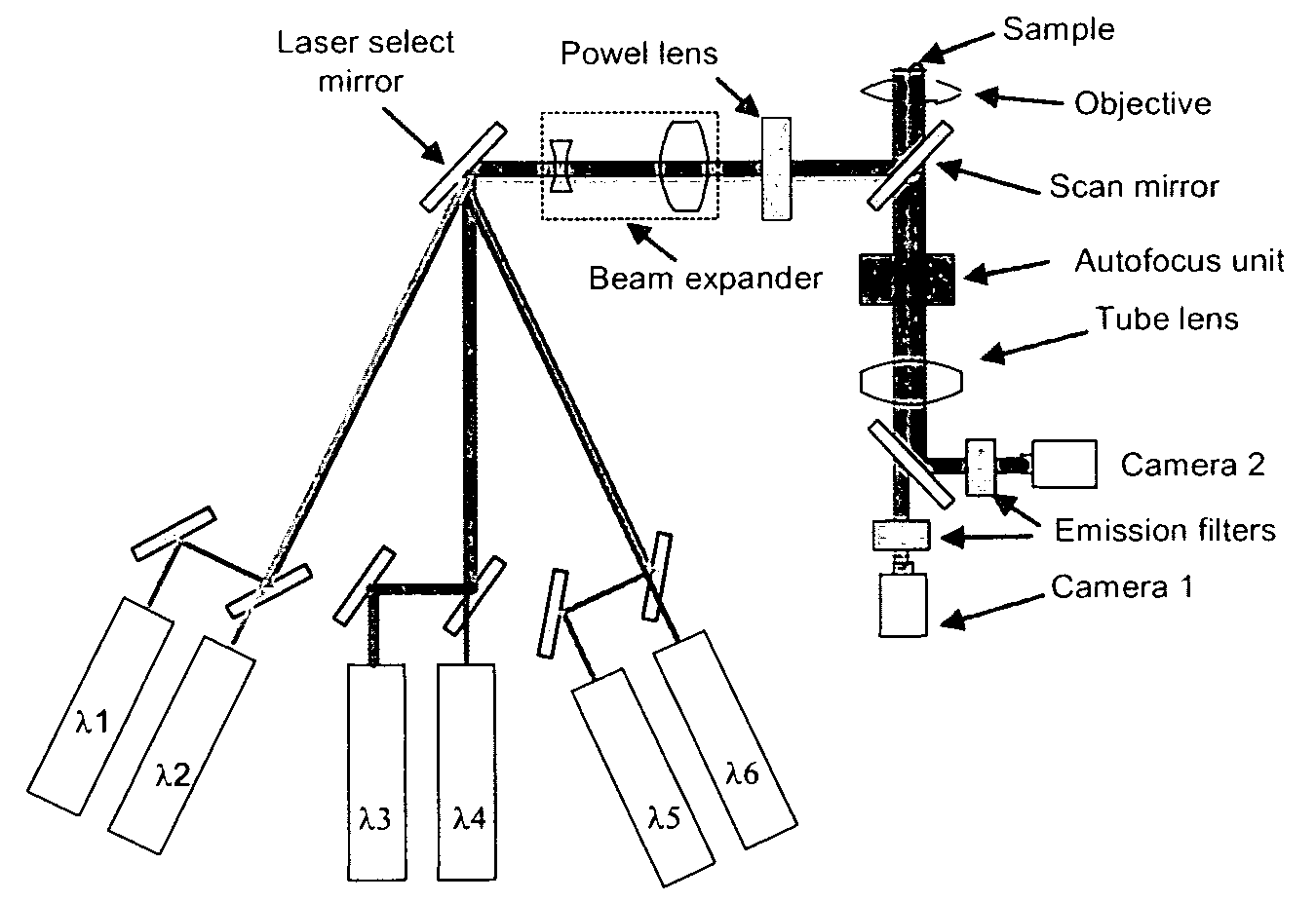
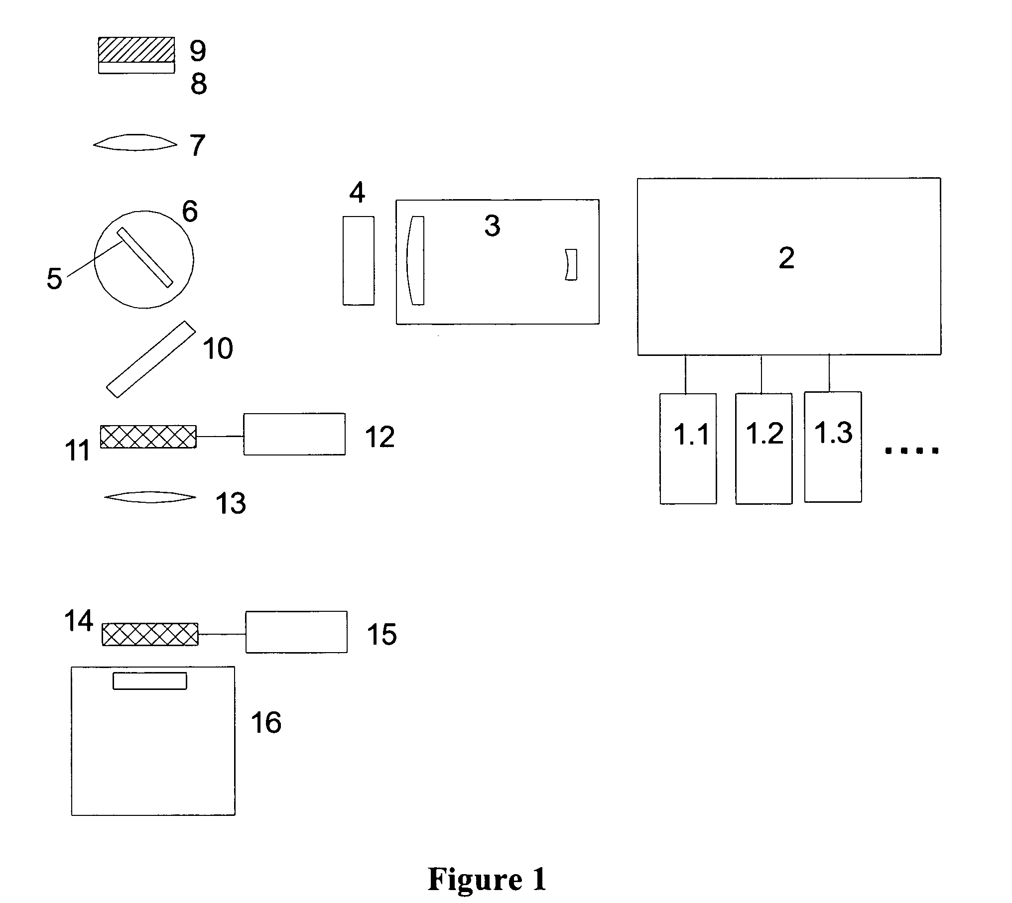
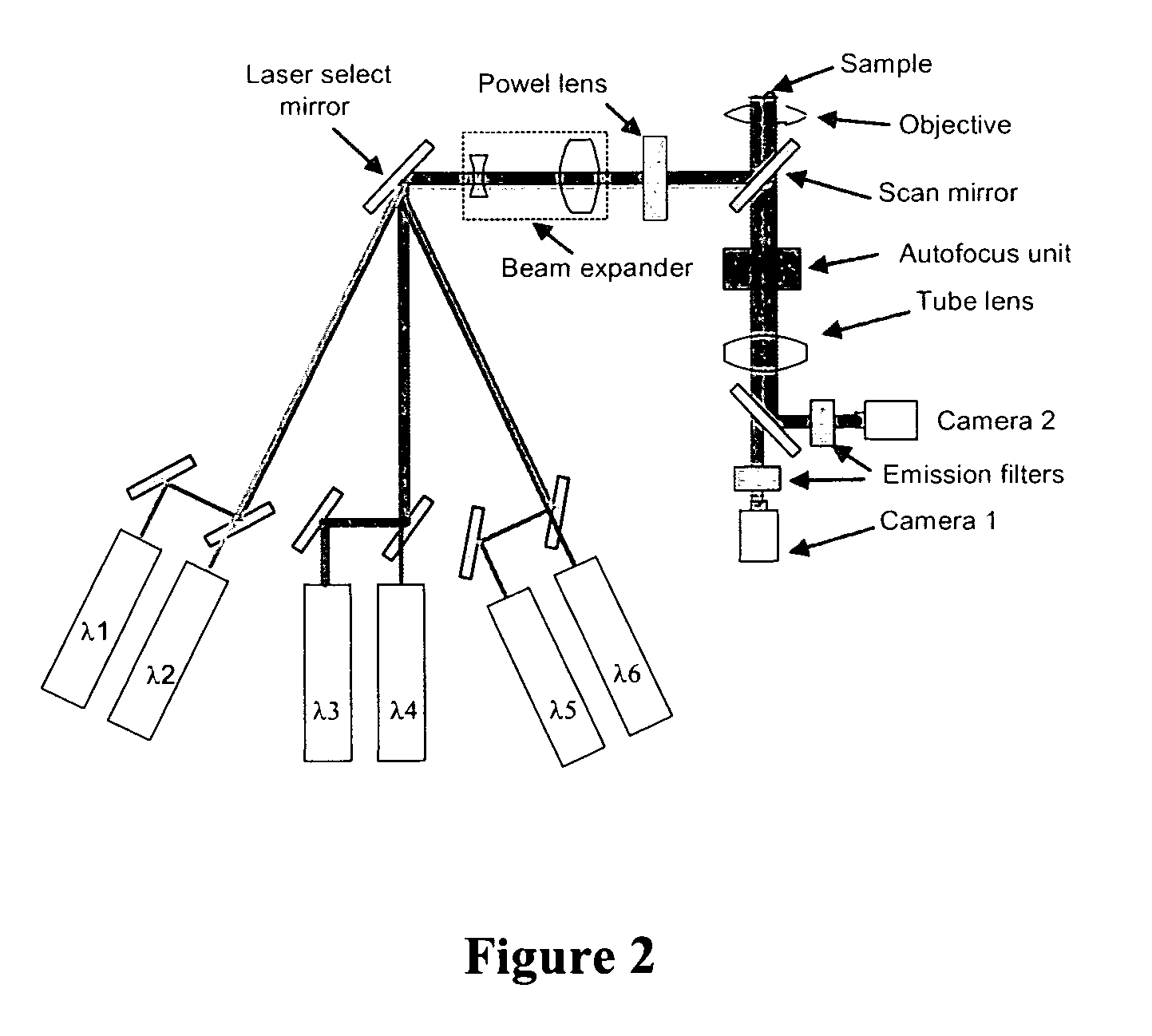
[0027]The instant confocal imaging system described previously, is schematically presented in FIG. 1, and includes, as described previously one or more light sources to excite a fluorescent (or fluorescently stained or labelled) target and a one or more detectors to detect fluorescent emissions. The system may contain other components as would ordinarily be found in confocal and wide field microscopes. The following sections describe these and other components in more detail. For a number of the components there are multiple potential embodiments. In general the preferred embodiment depends upon the target application. For the purpose of this document the preferred target application is a high throughput cellular screening with the ability to image a wide range of fluorophores.

Description of Components

Laser Sources

[0028]While the light source can, as described previously, be any source capable of delivering light of the excitation wavelength to the target, preferably one or more exc...


PUM

PropertyMeasurementUnit
thicknessaaaaaaaaaa
thicknessaaaaaaaaaa
focal lengthaaaaaaaaaa

Abstract

A new and improved confocal fluorescence microscope is presented. The new microscope has significant advantages relative to existing implementations of microscope confocal imagers. In common with previous confocal imagers the instant invention has the advantages relative to conventional wide-field and confocal fluorescence imagers, however it addresses the drawbacks of confocal technology in terms of cost and complexity, and provides significant savings in both due to the simplicity of the components and the elimination of the need of, in particular, spatial filters such as pinholes or slits.

Description

BACKGROUND OF INVENTION[0001]The present invention relates to the area of optical microscopy, more specifically, the area of confocal fluorescence microscopy, and methods of obtaining images of fluorescently labelled targets by confocal fluorescence microscopy.[0002]Generally, most fluorescence microscopes can be categorized into one of the following general classes based on how the fluorescent image information is captured and processed:[0003]Wide-field Microscopes[0004]In these microscopes, the target is imaged using a conventional wide-field strategy as in any standard microscope, and collecting the fluorescence emission. Generally, the fluorescent-stained or labelled sample is illuminated with excitation light of the appropriate wavelength(s) and the emission light is used to obtain the image; optical filters and / or dichroic mirrors are used to separate the excitation and emission light.[0005]Structured Light Microscopes[0006]This is a modification of a microscope that provides ...

Claims


Application Information

Patent Timeline
Patent Type & Authority Patents(United States)
IPC IPC(8): G01N21/64
CPCG02B21/0036G02B21/0084G02B21/0076G02B21/0064
Inventor DONDERS, PAULZARATE, CARLOSFOMITCHOV, PAVEL A.
Owner LEICA MICROSYSTEMS CMS GMBH
Why Eureka
Try Eureka