Circuit and method for controlling a DC-DC converter by enabling the synchronous rectifier during undervoltage lockout

a synchronous rectifier and synchronous rectifier technology, applied in the direction of process and machine control, pulse technique, instruments, etc., can solve the problems of error amplifier lag, burnout, etc., and achieve the effect of preventing deficiencies

Active Publication Date: 2008-02-26
SOCIONEXT INC
View PDF14 Cites 24 Cited by
  • Summary
  • Abstract
  • Description
  • Claims
  • Application Information

AI Technical Summary

Benefits of technology

[0018]The present invention provides a circuit and method for controlling a DC-DC converter that prevents deficiencies when a sudden interruption of the power supply voltage occurs.

Problems solved by technology

This may cause a deficiency, such as latch-up or burnout, in the error amplifier 4a.

Method used


Image

  • Circuit and method for controlling a DC-DC converter by enabling the synchronous rectifier during undervoltage lockout
  • Circuit and method for controlling a DC-DC converter by enabling the synchronous rectifier during undervoltage lockout
  • Circuit and method for controlling a DC-DC converter by enabling the synchronous rectifier during undervoltage lockout

Examples


first embodiment

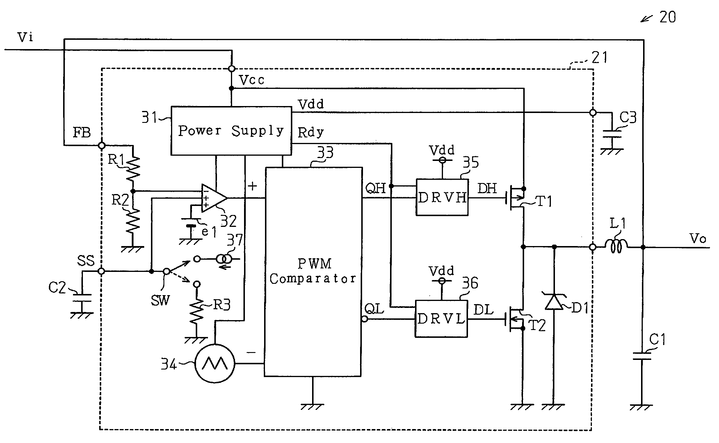
[0034]A DC-DC converter 20 according to the present invention will now be described with reference to FIGS. 3 to 5. The DC-DC converter 20 is incorporated in a portable electronic device (e.g., notebook personal computer) to convert an input voltage Vin supplied from a battery to a constant output voltage Vo for operating internal circuits such as a CPU.

[0035]The DC-DC converter 20, which is a voltage control DC-DC converter, includes a control circuit 21 formed on a single-chip integrated circuit board, a choke coil L1, a smoothing capacitor C1, a soft-start capacitor C2, and a power supply capacitor C3. The choke coil L1 and capacitors C1, C2 and C3 function as externally connected devices.

[0036]The choke coil L1 has a first terminal connected to the output terminal of the control circuit 21 and a second terminal connected to a semiconductor integrated circuit device (not shown), which functions as a load. The control circuit 21 supplies the output voltage Vo to the load via the c...

second embodiment

[0074]A DC-DC converter 40 according to the present invention will now be described with reference to FIG. 6.

[0075]The DC-DC converter 40 includes a control circuit 41 formed on a single-chip integrated circuit board. The DC-DC converter 40 further includes output transistors T1 and T2, a choke coil L1, a smoothing capacitor C1, a soft-start capacitor C2, and a power supply capacitor C3, each of which functions as an externally connected device. Unlike the control circuit 2 of the first embodiment, the control circuit 41 of the second embodiment does not have the output transistors T1 and T2. In the second embodiment, the output transistors T1 and T2 are connected to the control circuit 41 as the externally connected devices. Accordingly, the DC-DC converter 40 of the second embodiment has the same advantages as the DC-DC converter 20 of the first embodiment.

third embodiment

[0076]A DC-DC converter 50 according to the present invention will now be described with reference to FIGS. 7 and 8.

[0077]The DC-DC converter 50 includes a control circuit 51 formed on a single-chip integrated circuit board. The DC-DC converter 50 further includes an output transistor (main switching transistor) T21, an output transistor (synchronous rectification transistor) T22, a choke coil L1, a smoothing capacitor C1, a soft-start capacitor C2, power supply capacitors C3 and C4, and diode D1 and D2, each of which functions as an externally connected device.

[0078]The output transistors T21 and T22 are both N-channel MOS transistors. The on resistance is decreased by configuring the output transistor T21 with an N-channel MOS transistor. This reduces power loss. The DC-DC converter 50 of the third embodiment is configured to drive the output transistor T21, which is an N-channel MOS transistor.

[0079]When an N-channel MOS transistor is employed as the output transistor T21 of the ...


PUM


Abstract

A control circuit for a DC-DC converter that prevents a deficiency from occurring due to sudden interruption in power supply. The control circuit activates and inactivates a main switching output transistor and a synchronous rectification output transistor to convert the input voltage to an output voltage. The output voltage is smoothed by a smoothing capacitor. When the input voltage decreases, the control circuit activates the synchronous rectification output transistor to readily discharge the smoothing capacitor via the synchronous rectification output transistor.

Description

CROSS-REFERENCE TO RELATED APPLICATIONS[0001]This application is based upon and claims the benefit of priority from the prior Japanese Patent Application No. 2005-103940, filed on Mar. 31, 2005, the entire contents of which are incorporated herein by reference.BACKGROUND OF THE INVENTION[0002]The present invention relates to a DC-DC converter, and more particularly, to a circuit and method for controlling a DC-DC converter.[0003]A portable electronic device, such as a notebook type personal computer and a gaming device, is provided with a plurality of semiconductor integrated circuit devices and a battery for supplying operational power to the plurality of semiconductor integrated circuit devices. Since the output voltage decreases as the battery discharges, a DC-DC converter is used to keep the operational power voltage constant.[0004]FIG. 1 is a schematic circuit diagram showing a first example of a voltage control DC-DC converter 1 in the prior art. The DC-DC converter 1 includes...

Claims


Application Information

Patent Timeline
Patent Type & Authority Patents(United States)
IPC IPC(8): G05F5/00H02H3/24H02H7/00
CPCH02M1/32H02M3/157H02M3/1588Y02B70/1466H03K17/22H03K2217/0081Y02B70/10H02M3/155
Inventor ITO, HIDENOBU
Owner SOCIONEXT INC
Why Eureka
Try Eureka