Method for designing RF excitation pulses in magnetic resonance tomography

a technology of excitation pulses and magnetic resonance tomography, which is applied in the direction of magnetic measurements, instruments, measurement devices, etc., can solve the problems of reducing the signal-to-noise ratio (snr) and image contrast, affecting the quality of rf excitation pulses, etc., to achieve better results

Inactive Publication Date: 2008-02-26
THE GENERAL HOSPITAL CORP +2
View PDF5 Cites 28 Cited by
  • Summary
  • Abstract
  • Description
  • Claims
  • Application Information

AI Technical Summary

Benefits of technology

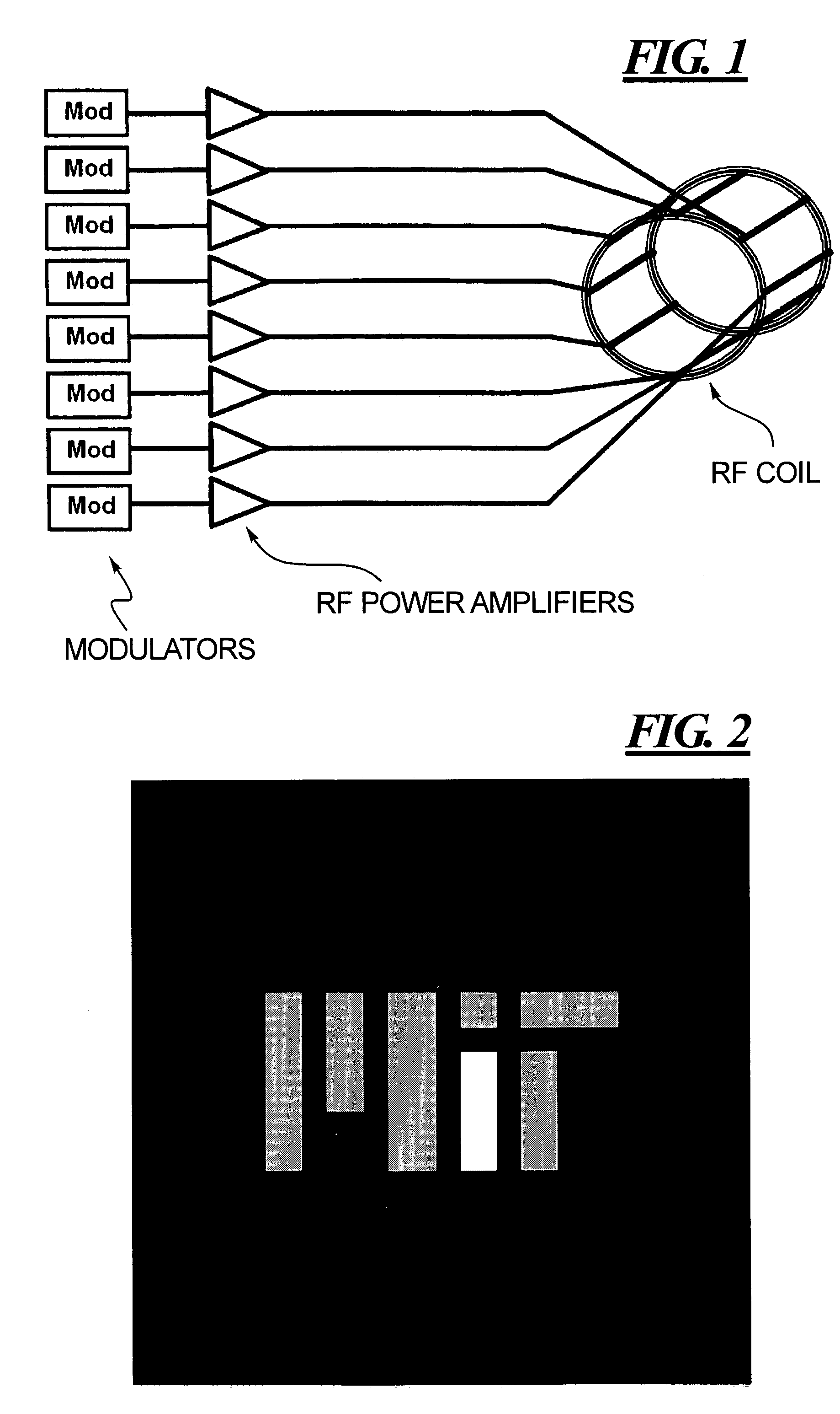
[0015]An object of the present invention is to provide a method for designing waveforms of radio-frequency pulses for a magnetic resonance imaging employing parallel RF excitation via multiple channels, which produces better results than the conventional SVD-based methods.
[0018]Using LSQR or CGLS to solve a linearized system of parallel RF design equations results in better excitations—both qualitatively and quantitatively—than those yielded via the traditional SVD-based method. This holds whenever the acceleration factor of the k-space trajectory is greater than one. In addition to improved artifact levels, the LSQR and CGLS designs use significantly lower peak and RMS voltage compared to SVD-based designs.

Problems solved by technology

The use of a single RF transmit channel imposes limitations in several applications of MR imaging, such as high-field and whole body imaging.
Some of the many negative consequences of high SAR are that the flip angle cannot be set to the desired value, which degrades the signal-to-noise ratio (SNR) and image contrast, the SAR online supervision switches off the RF power during the measurement, thereby delaying or stopping the scan, artificial limits are imposed on the number of achievable slices, and an increase in repetition time (TR) is required, which translates into longer scan times.
Furthermore, conventional RF design algorithms lead to higher artifact levels in images due to their poor numerical properties.
For example, images may exhibit incomplete background suppression, poor spin cancellation, or suboptimal excitation of desired target regions.
The primary limitation of such an excitation is the length of time needed for the pulse.

Method used


Image

  • Method for designing RF excitation pulses in magnetic resonance tomography
  • Method for designing RF excitation pulses in magnetic resonance tomography
  • Method for designing RF excitation pulses in magnetic resonance tomography

Examples


Embodiment Construction

[0029]First, parallel excitation RF waveform design is discussed, followed by a discussion of three algorithms for (approximately) solving a linear system of equations.

[0030]The equations describing the interaction between the RF waveforms played along each coil array and the resulting excitation pattern are nonlinear and complicated. Thus, it is desirable to reduce the system of equations in some manner to simplify the overall RF design process.

[0031]Grissom et al. simplify RF design for parallel systems by first applying a parallel small-tip angle approximation to the original set of equations and then discretizing the result in the spatial and temporal dimensions [3]. The use of the small-tip angle approximation is greatly beneficial because it reduces the RF design problem from a set of nonlinear equations to a set of linear ones that contains a Fourier transform. The linearized excitation due to P coils is written as follows:

[0032]m⁡(r)=ⅈ⁢⁢γ⁢∑p=1P⁢⁢Sp⁡(r)⁢∫0T⁢B1,p⁡(t)⁢ⅇⅈr·k⁡(t)...


PUM


Abstract

Waveforms for radio-frequency (RF) excitations pulses used in magnetic resonance imaging are designed according to a Least Squares QR (LSQR) algorithm or a Conjugate Gradient Least Squares (CGLS) algorithm, to solve the linear system of equations that arises in a multi-channel RF transmit arrangement. Better management of SAR and other factors is achieved with RF pulses designed according to these algorithms, compared to the conventionally employed singular value decomposition (SVD) algorithm.

Description

FEDERAL FUNDING LEGEND[0001]This invention was produced in part using funds from the Federal government from National Institutes of Health P41RR14075, United States Department of Defense (National Defense Science and Engineering Graduate Fellowship), R. J. Shillman Career Development Award. Accordingly, the Federal government has certain rights in this invention.BACKGROUND OF THE INVENTION[0002]1. Field of the Invention[0003]The present invention relates to a method for designing waveforms of RF pulses for use in an excitation sequence in magnetic resonance tomography.[0004]2. Description of the Prior Art[0005]Currently clinical magnetic resonance (MR) systems use a single RF transmitting channel for emitting radio-frequency pulses to excite nuclear spins in an examination subject. The use of a single RF transmit channel imposes limitations in several applications of MR imaging, such as high-field and whole body imaging.[0006]The use of multiple, independent RF modulators and RF coi...

Claims


Application Information

Patent Timeline
Patent Type & Authority Patents(United States)
IPC IPC(8): G01V3/00
CPCG01R33/5611G01R33/5612G01R33/5659G01R33/288G01R33/3415
Inventor ZELINSKI, ADAM CHARLESADALSTEINSSON, ELFARSETSOMPOP, KAWINWAID, LAWRENCE L.FONTIUS, JOERG ULRICH
Owner THE GENERAL HOSPITAL CORP
Why Eureka
Try Eureka