Particle analyzing system and methodology

a particle analysis and particle technology, applied in the field of image and optical systems, can solve the problems of difficulty in viewing images on the monitor, the display of machine-vision or computer-based image displays of the above image sensors on the monitor or other output display devices is not of quality perceived by the human observer through the eyepiece, etc., to facilitate the imaging performance of optical imaging systems, increase the effective resolution of magnification, and increase the working distance

Inactive Publication Date: 2008-03-04
PIXEL MATCHED HLDG
View PDF35 Cites 79 Cited by
  • Summary
  • Abstract
  • Description
  • Claims
  • Application Information

AI Technical Summary

Benefits of technology

[0007]The present invention relates to a system and methodology that facilitates imaging performance of optical imaging systems. In regard to several optical and / or imaging system parameters, many orders of performance enhancement can be realized over conventional systems (e.g., greater effective resolved magnification, larger working distances, increased absolute spatial resolution, increased spatial field of view, increased depth of field, Modulation Transfer Function of about 1, oil immersion objectives and eye pieces not required). This is achieved by adapting an image transfer medium (e.g., one or more lenses, fiber optical media, or other media) to a sensor having one or more receptors (e.g., photodetectors, pixels) such that the receptors of the sensor are effectively scaled (e.g., “mapped”, “sized”, “projected”, “matched”, “reduced”) to occupy an object field of view at about the scale or size associated with a diffraction limited point or spot within the object field of view. Thus, a band-pass filtering of spatial frequencies in what is known as Fourier space or “k-space” is achieved such that the projected size (projection in a direction from the sensor toward object space) of the receptor is filled in k-space.

Problems solved by technology

Connecting a Machine Vision Sensor, such as a Charge Coupled Device (CCD) sensor, to the microscope so that an image may be viewed on a monitor presents difficulties.
As a result, conventional optical systems for magnifying, observing, examining, and analyzing small items often require the careful attention of a technician monitoring the process through an eyepiece.
It is for this reason, as well as others, that Machine-Vision or computer-based image displays from the aforementioned image sensor displayed on a monitor or other output display device are not of quality perceived by the human observer through the eyepiece.

Method used


Image

  • Particle analyzing system and methodology
  • Particle analyzing system and methodology
  • Particle analyzing system and methodology

Examples


Embodiment Construction

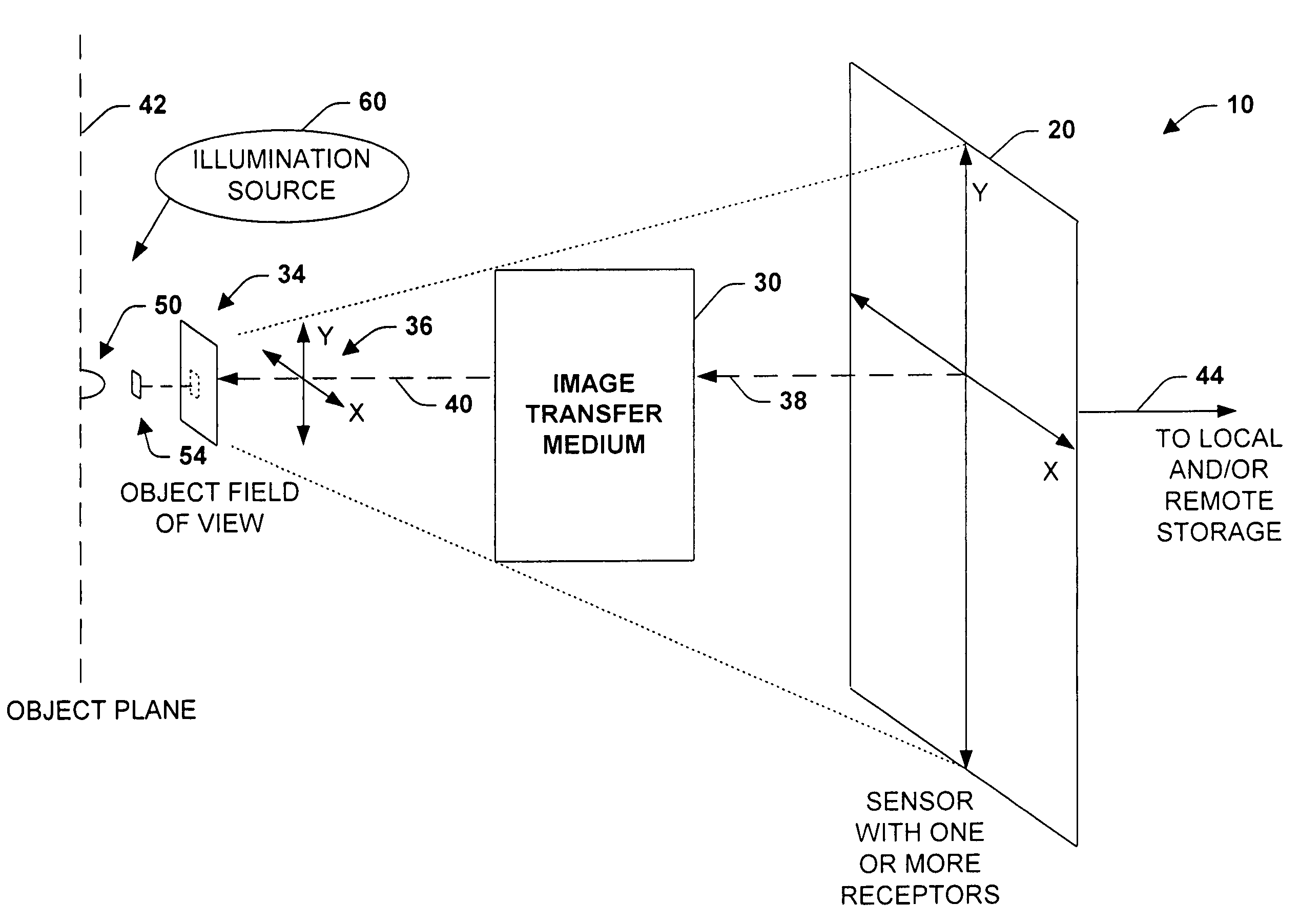
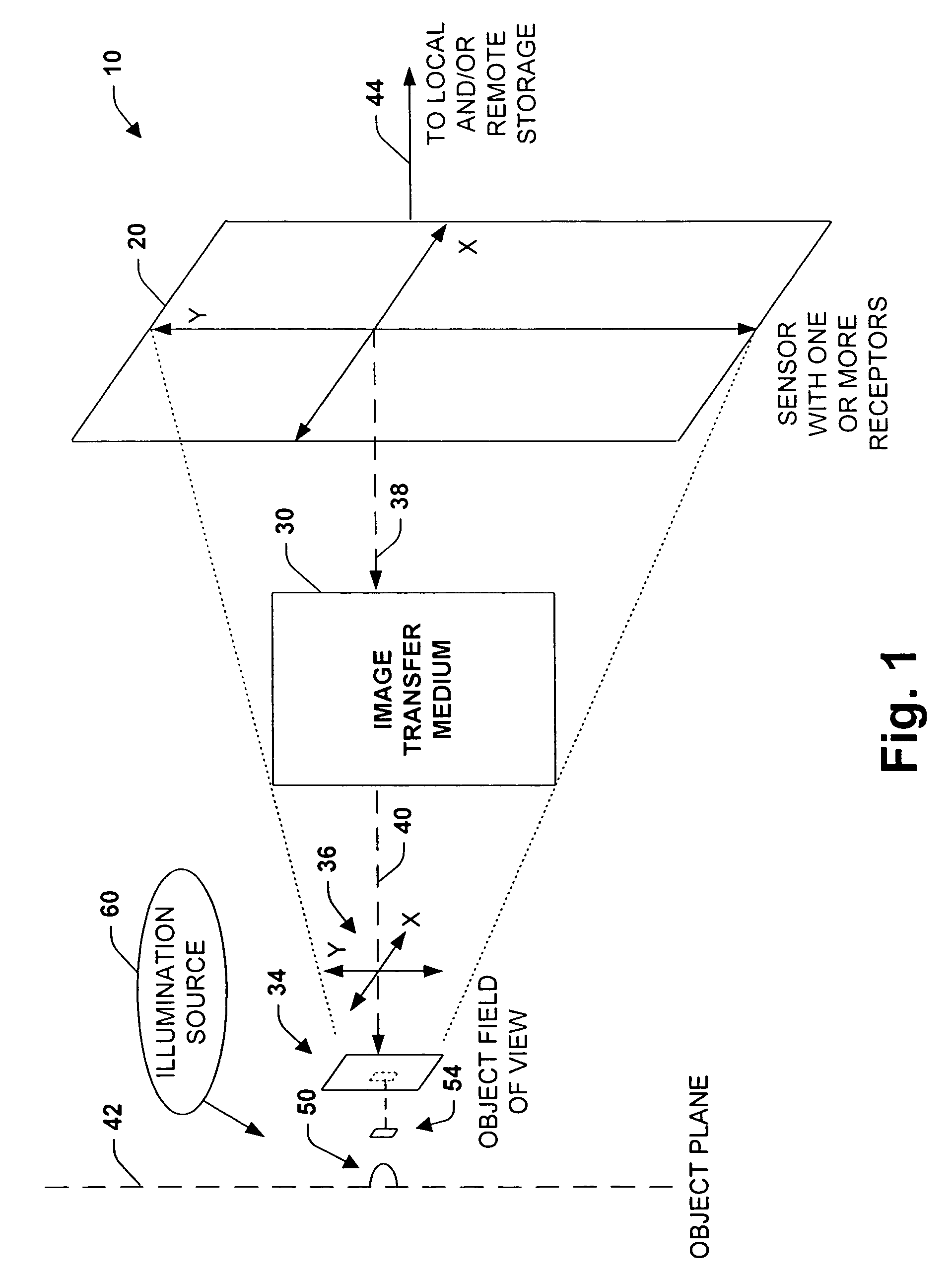
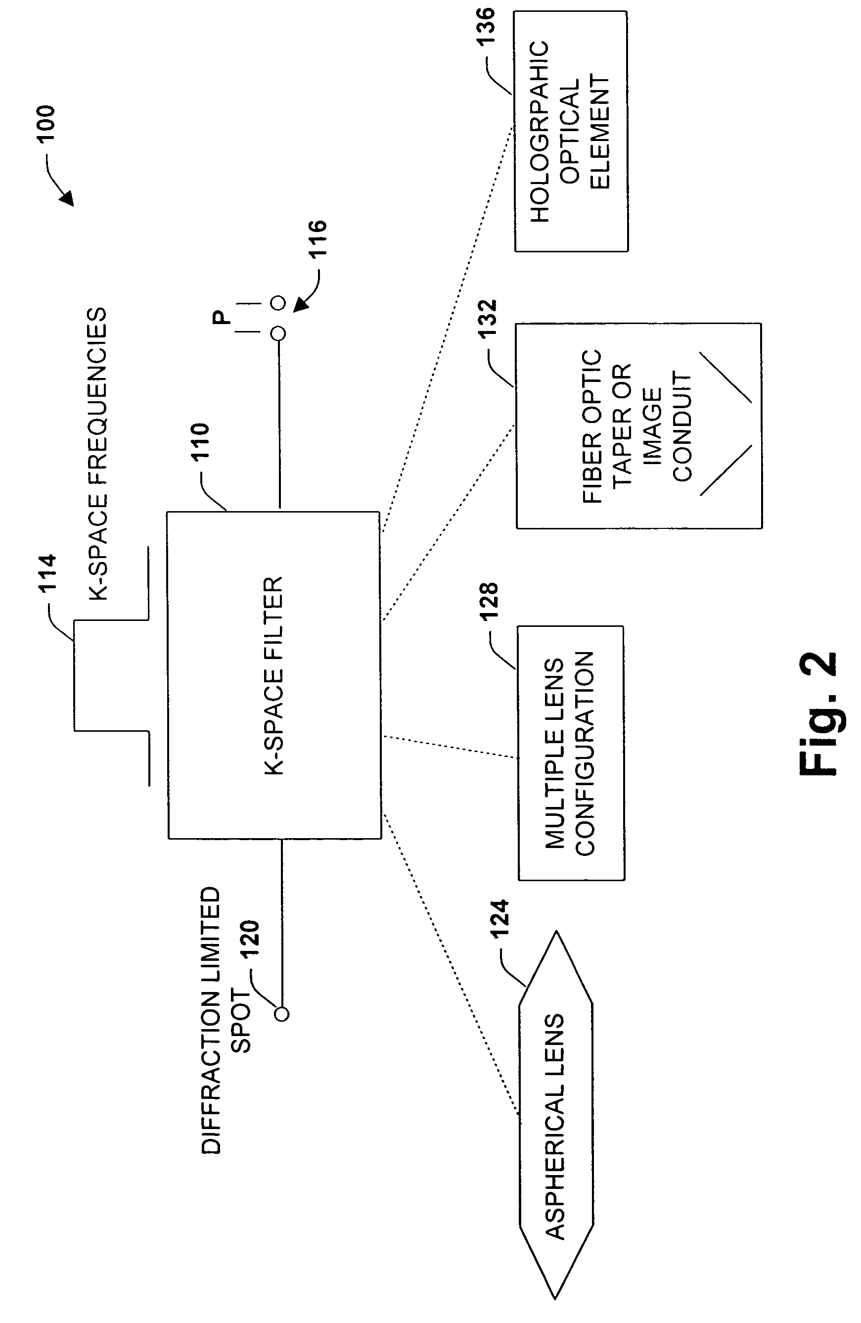
[0032]The present invention relates to an optical and / or imaging system and methodology. According to one aspect of the present invention, a k-space filter is provided that can be configured from an image transfer medium such as optical media that correlates image sensor receptors to an optical or image transfer medium. A variety of illumination sources can also be employed to achieve one or more operational goals and for versatility of application. The k-space design of the imaging system of the present invention promotes capture and analysis (e.g., automated and / or manual) of images having a high Field Of View (FOV) at substantially high Effective Resolved Magnification as compared to conventional systems. This can include employing a small Numerical Aperture (NA) associated with lower magnification objective lenses to achieve very high Effective Resolved Magnification. As a consequence, images having a substantially large Depth Of Field (DOF) at very high Effective Resolved Magni...


PUM

PropertyMeasurementUnit
wavelength rangeaaaaaaaaaa
Working Distanceaaaaaaaaaa

Abstract

An imaging system, methodology, and various applications are provided to facilitate optical imaging performance. The system contains a sensor having one or more receptors and an image transfer medium to scale the sensor and receptors in accordance with resolvable characteristics of the medium, and as defined with certain ratios. A computer, memory, and / or display associated with the sensor provides storage and / or display of information relating to output from the receptors to produce and / or process an image, wherein a plurality of illumination sources can also be utilized in conjunction with the image transfer medium. The image transfer medium can be configured as a k-space filter that correlates receptor size to a diffraction-limited spot associated with the image transfer medium, wherein the receptor size can be unit-mapped within a certain ratio to the size of the diffraction-limited spot.

Description

RELATED APPLICATIONS[0001]This application is a continuation-in-part of U.S. patent application of Ser. No. 10 / 616,829 which was filed Jul. 10, 2003 now U.S. Pat. No. 7,248,716 entitled IMAGING SYSTEM, METHODOLOGY, AND APPLICATIONS EMPLOYING RECIPROCAL SPACE OPTICAL DESIGN, which is a continuation-in-part of U.S. patent application Ser. No. 10 / 189,326 which was filed Jul. 2, 2002 now U.S. Pat. No. 7,132,636 entitled IMAGING SYSTEM AND METHODOLOGY EMPLOYING RECIPROCAL SPACE OPTICAL DESIGN, which is a continuation-in-part of U.S. patent application Ser. No. 09 / 900,218, which was filed Jul. 6, 2001 now U.S. Pat. No. 6,664,528, entitled IMAGING SYSTEM AND METHODOLOGY EMPLOYING RECIPROCAL SPACE OPTICAL DESIGN, all of which are incorporated herein by reference.TECHNICAL FIELD[0002]The present invention relates generally to image and optical systems, and more particularly to a system and method to facilitate imaging performance via an image transfer medium that projects characteristics of ...

Claims


Application Information

Patent Timeline
Patent Type & Authority Patents(United States)
IPC IPC(8): A61B3/14G01N23/04G01N15/02G01N21/00G01V8/00G06K9/76G06T3/00H01L27/00H04N5/225
CPCG01N21/6458G01N21/9501G02B21/361G06T3/40G01N15/1475G01N2015/1479G01N2015/1497
Inventor CARTLIDGE, ANDREW G.FEIN, HOWARD
Owner PIXEL MATCHED HLDG
Why Eureka
Try Eureka