Voltage-controlled oscillator with multi-phase realignment of asymmetric stages

a voltage control and asymmetric stage technology, applied in the direction of electrial characteristics varying frequency control, pulse generator, pulse technique, etc., can solve the problems of low-frequency phase modulation (pm) noise, long-term jitter, significant and cumulative, etc., to achieve constant time

Inactive Publication Date: 2008-03-04
ATMEL CORP
View PDF19 Cites 21 Cited by
  • Summary
  • Abstract
  • Description
  • Claims
  • Application Information

AI Technical Summary

Benefits of technology

[0007]The present invention uses parallel charge injection into each stage of a VCO circuit to apply a distributed and simultaneous phase shift to each stage in the ring at the instant the alignment is necessary. Each of the individual stages generates a waveform in which the rise times differ from the fall times. As a result of this rise-fall asymmetry in the waveforms from the individual stages, a multiphase impulse sensitivity response function is obtained for the VCO circuit as a whole that is both strictly positive (or, strictly negative) and also relatively constant in time. Short current impulses are applied in parallel to each of the stages in order to induce phase shifts at the output of each stage relative to the phase angle before the realignment. Although the magnitude and direction of the phase shift obtained from each individual stage will depend upon the instantaneous phase of the particular stage, the relatively constant multiphase response allows an overall phase shift from the VCO as a whole that is largely independent of the timing of those current impulses. Accordingly, phase realignment is readily achieved without needing any special synchronization between the reference clock and the VCO internal signals or clock output signal.

Problems solved by technology

In classical VCO structures, low-frequency phase modulation (PM) noise, or long-term jitter, is significant and cumulative.
Enlarging the PLL bandwith is limited by the fact that the bandwidth cannot exceed about 1 / 20th of the reference frequency, due to quantization noise.
The addition of realignment inverters adds phase delay to the VCO ring and thus decreases the VCO circuit's maximum operating frequency.
The device parameters in any VCO circuit embodiment are specific to the design operating frequency, and hence this particular phase realignment technique is not applicable where a VCO circuit with a wide frequency range is desired.
But, the system is too slow for operations at high frequencies.

Method used


Image

  • Voltage-controlled oscillator with multi-phase realignment of asymmetric stages
  • Voltage-controlled oscillator with multi-phase realignment of asymmetric stages
  • Voltage-controlled oscillator with multi-phase realignment of asymmetric stages

Examples


Embodiment Construction

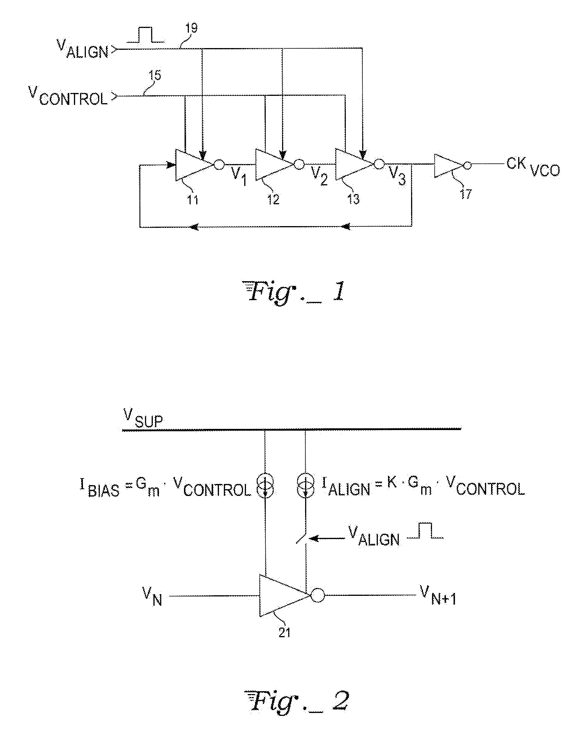
[0023]With reference to FIG. 1, a three-stage ring voltage-controlled oscillator (VCO) circuit includes a series of inverting stages 11, 12, and 13, with the output of the third stage 13 coupled back to the input of the first stage 11. Each of the stages 11, 12, and 13 outputs an oscillating voltage, V1, V2, and V3, respectively, which will be essentially periodic over time. The number of stages can vary.

[0024]The oscillation frequency of the output voltages, V1, V2, and V3, depends on the propagation delay through one cycle of the ring and can be adjusted to a target frequency using a control voltage VCONTROL applied via a control input line 15 to each of the stages 11, 12, and 13. The oscillating output voltages from the three stages will have relative phases that tend to be 120° apart (except immediately after a realignment impulse).

[0025]A high gain output stage 17 drives the signal received from the ring stages to saturation so that it generates a VCO clock output CKVCO that is...


PUM


Abstract

A multi-phase realigned voltage-controlled oscillator (MRVCO) achieves phase realignment based on charge injection in the VCO stages. The individual VCO stages provide an oscillating output signals having an asymmetric waveform with substantially different rise and fall times. This ensures that the VCO as a whole has a multiphase impulse response to the charge injection that is strictly positive or strictly negative, and substantially constant so as to be independent of the VCO phase or timing of charge injection. The MRVCO may form a component part of an implementation of a multi-phase realigned phase-locked loop (MRPLL).

Description

CROSS-REFERENCE TO RELATED APPLICATION[0001]This is a continuation-in-part of prior U.S. application Ser. No. 11 / 183,346, filed Jul. 18, 2005, now U.S. Pat. No. 7,126,432.TECHNICAL FIELD[0002]The present invention relates to voltage-controlled oscillator (VCO) circuits, especially those of the ring oscillator type, characterized by recurring phase realignment with respect to a reference signal. The invention also relates to phase-locked loops containing such a VCO as a component itself.BACKGROUND ART[0003]In classical VCO structures, low-frequency phase modulation (PM) noise, or long-term jitter, is significant and cumulative. Phase-locked loop (PLL) circuits using this kind of VCO are able to correct this PM noise or jitter only up to a modulation frequency equal to that of the PLL band width. At higher modulation frequencies, the PLL circuit stops regulating and so the PM noise is equal to or slightly higher than the intrinsic PM noise of the VCO. Reducing high frequency PM noise,...

Claims


Application Information

Patent Timeline
Patent Type & Authority Patents(United States)
IPC IPC(8): H03B5/24H03L7/087H03L7/099
CPCH03K3/0315H03L7/083H03L7/087H03L7/0995H03L7/0891
Inventor ROUBADIA, REGISAJRAM, SAMI
Owner ATMEL CORP
Why Eureka
Try Eureka