Active noise control system

a technology of active noise control and control system, which is applied in the direction of active noise control, transportation and packaging, instruments, etc., can solve the problems of unstable operation of adaptive notch filter, confined engine noise that is noticeable periodicity, and resonance to occur in the passenger compartment, so as to prevent overcompensation, suppress divergence, and ideal noise reduction

Active Publication Date: 2008-03-04
PANASONIC CORP +1
View PDF7 Cites 21 Cited by
  • Summary
  • Abstract
  • Description
  • Claims
  • Application Information

AI Technical Summary

Benefits of technology

[0013]The present invention is to overcome the aforementioned problems. It is therefore an object of the present invention to provide an active noise control system, which updates the filter coefficient of an adaptive notch filter with stability while suppressing divergence, and prevents overcompensation to provide passengers with an ideal noise reduction effect. The system is designed to provide these functions even under the

Problems solved by technology

The confined engine noise is a radiant noise which is generated by a vibrational force, created by the operation of the engine of a vehicle, being transferred to the vehicle body and thus causing resonance to occur in the passenger compartment or a closed space under a certain condition.
Thus, the confined engine noise has noticeable periodicity in synchronization with the rotational speed or frequency of the engine.
Under these circumstances, the active noise control system may operate causing an unstable operation of the adaptive notch filter.
This would not only make it difficult to provide an ideal noise reduction effect but also bring the system into divergence causing a noise to be further increased.
Furthermore,

Method used


Image

  • Active noise control system
  • Active noise control system
  • Active noise control system

Examples


first embodiment

[0030]Now, the present invention will be explained below in more detail with reference to the accompanying drawings in accordance with the embodiments. In the drawings, the same components as those of the conventional active noise control system described in relation to the related art are indicated by the like reference symbols. By way of example, the present invention will be described in accordance with an active noise control system incorporated into a vehicle to reduce a vibrational noise in the passenger compartment caused by the operation of the engine.

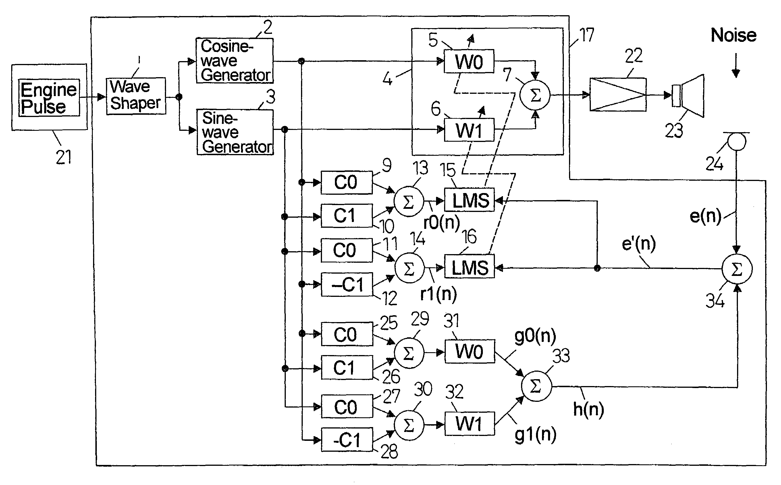
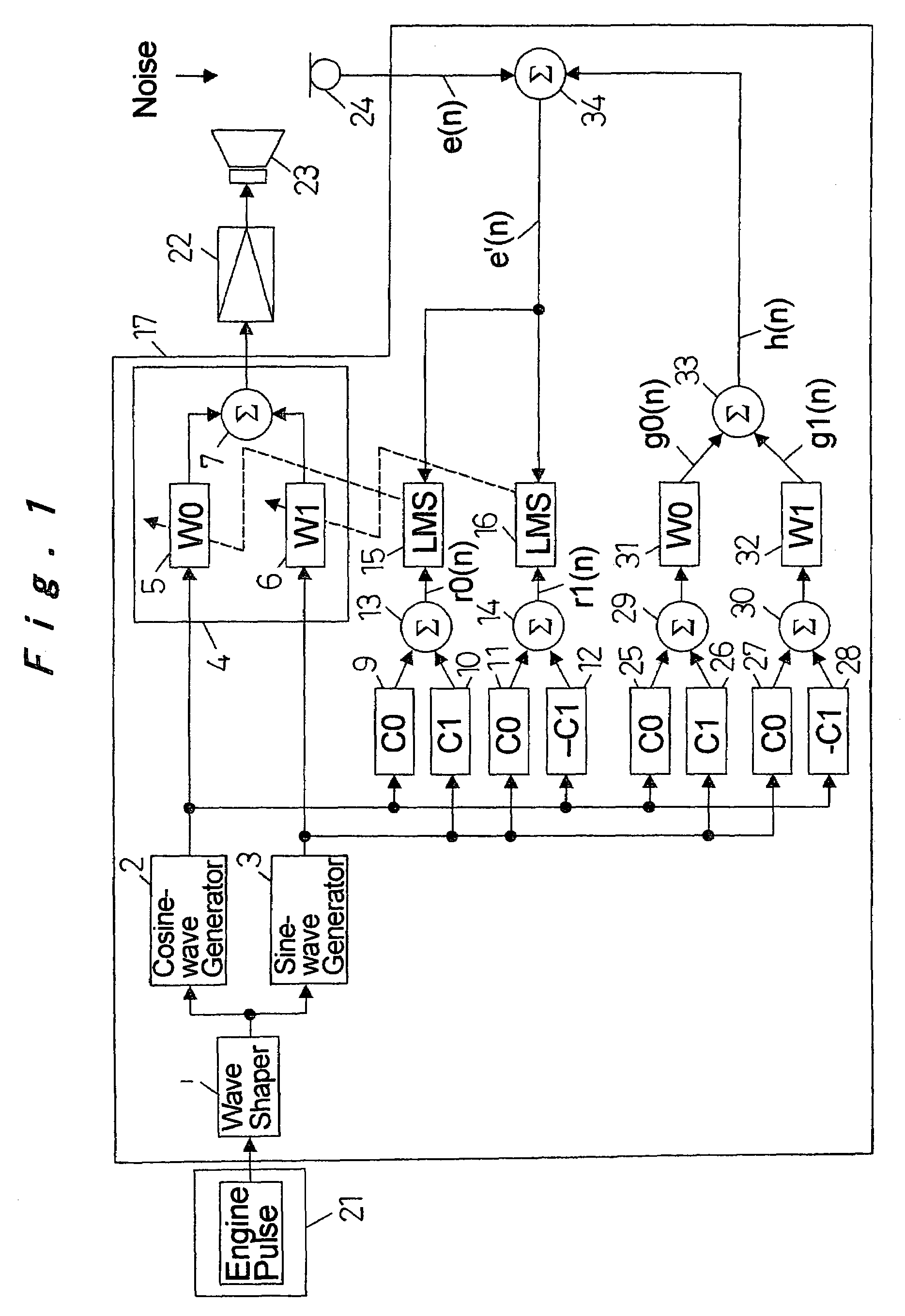
[0031]FIG. 1 illustrates in a block diagram form the configuration of an active noise control system according to the first embodiment. Referring to FIG. 1, with an engine 21 being a noise source that generates a problematic noise, the active noise control system operates to reduce a periodic vibrational noise radiated by the engine 21.

[0032]An engine pulse or an electric signal synchronous with the rotation of the engine 21 is...

second embodiment

[0059]In accordance with the aforementioned first embodiment, described was that the added signal of the compensated signal “h” and the output signal (error signal “e”) from the microphone 24 is used in an adaptive control algorithm to update the filter coefficients W0 and W1 of the adaptive notch filter 4, thereby suppressing overcompensation and providing enhanced control stability. In the second embodiment, a description will be further made to a technique for controlling the amount of suppression of overcompensation.

[0060]FIG. 7 illustrates in a block diagram form the configuration of an active noise control system according to the second embodiment. In the figure, the same components as those of the active noise control system shown in the first embodiment are indicated by the like reference symbols.

[0061]FIG. 7 is different from FIG. 1 in that the compensated signal generator means is provided with a coefficient multiplier 35. With this arrangement, the compensated signal “h” ...

third embodiment

[0070]FIG. 9 illustrates in a block diagram form the configuration of an active noise control system according to the third embodiment. In the figure, the same components as those of the active noise control systems shown in the first and second embodiments are indicated by the like reference symbols.

[0071]FIG. 9 is different from FIG. 7 in that the compensated signal generator means is provided with an output control portion 36. With this arrangement, an output signal K·h from the coefficient multiplier 35 is supplied to the output control portion 36. The output control portion 36 includes a storage area for storing the values of the filter coefficient W0 of the first one-tap adaptive filter 5 each time the filter coefficient W0 is updated during a predetermined interval from a previous to the present point in time (e.g., an interval during which the filter coefficient is updated 20 times). The output control portion 36 calculates a cumulative amount of the changes. Similarly, the ...


PUM


Abstract

An active noise control system is provided which cancels a noise using a sound radiated from a speaker driven by an output from an adaptive notch filter. The system employs output signals from an adder or simulation cosine-wave and sine-wave signals, an error signal or an output signal from a microphone, and a compensated signal from the adder or a signal available for acoustically transferring an output from the adaptive notch filter to the microphone in accordance with initial transfer characteristics to update the filter coefficient of the adaptive notch filter. This configuration allows the system to operate with stability even when the acoustic transfer characteristics vary with time or under circumstances where there exists a significant amount of incoming external noises. The system also prevents overcompensation for a noise at the ears of a passenger in a vehicle, thereby proving an ideal noise reduction effect.

Description

[0001]The present disclosure relates to subject matter contained in priority Japanese Patent Application No. 2003-151827, filed on May 29, 2003, the contents of which is herein expressly incorporated by reference in its entirety.BACKGROUND OF THE INVENTION[0002]1. Field of the Invention[0003]The present invention relates to an active noise control system which produces a signal that is interfere with and attenuates an uncomfortable confined engine noise generated in the passenger compartment of a vehicle by the operation of the engine, the signal being equal in amplitude and opposite in phase with the confined engine noise.[0004]2. Description of the Related Art[0005]The confined engine noise is a radiant noise which is generated by a vibrational force, created by the operation of the engine of a vehicle, being transferred to the vehicle body and thus causing resonance to occur in the passenger compartment or a closed space under a certain condition. Thus, the confined engine noise ...

Claims


Application Information

Patent Timeline
IPC IPC(8): G10K11/16H03B29/00B60R11/02G10K11/178
CPCG10K11/1784G10K2210/101G10K2210/128G10K2210/3012G10K2210/511G10K11/17835G10K11/17854G10K11/17883
Inventor NAKAMURA, YOSHIOONISHI, MASAHIDEINOUE, TOSHIOTAKAHASHI, AKIRA
Owner PANASONIC CORP
Why Eureka
Try Eureka