Image intensifier and LWIR fusion/combination system

a fusion/combination system and image intensifier technology, applied in the field of infrared sensor devices, can solve the problems of display distortion, lwir sensor cryogenic cooling, and none of the prior night vision systems providing satisfactory field use performance, etc., and achieve the effect of eliminating parallax and eliminating parallax

Inactive Publication Date: 2008-03-18
ZHANG EVAN
View PDF27 Cites 67 Cited by
  • Summary
  • Abstract
  • Description
  • Claims
  • Application Information

AI Technical Summary

Benefits of technology

[0008]The present invention overcomes the disadvantages of previously known infrared imaging systems by providing an infrared imaging device that fuses / combines two sensors, each sensor is sensitive to a different spectral range of infrared radiation. Both sensors are combined in a single camera sharing a common aperture, and as such, parallax is eliminated between the sensors. Further, a display device is provided along an optical axis in common with the camera, thus eliminating parallax between the display and camera. Images from the first sensor, the second sensor, or both sensors may be viewed on the display. The infrared imaging fusion system of the present invention is mountable on a headgear such as a helmet or the like, and is arranged on the headgear such that the display is viewable by an operator wearing the headgear by directing the operator's gaze upward so that the display does not interfere with an operator's straight ahead and downward line of sight. The present invention can also be used with other mounting methods based upon the specific application of use, or in a handheld fashion.

Problems solved by technology

However, none of the prior night vision systems provide satisfactory performance for field use under harsh environmental conditions.
However, the LWIR sensor requires cryogenic cooling.
Otherwise, the display is distorted by temperature fluctuations of the sensor itself.
Cooling adds substantial cost and bulk to the LWIR sensor thus limiting the applications where cryogenically equipped LWIR sensors may be used.
Although the resolution of I2 is much better than LWIR, it does not function is well as the LWIR sensor in harsh environmental conditions such as in fog, haze, smoke, and complete darkness.

Method used


Image

  • Image intensifier and LWIR fusion/combination system
  • Image intensifier and LWIR fusion/combination system
  • Image intensifier and LWIR fusion/combination system

Examples


Embodiment Construction

[0039]In the following detailed description of the preferred embodiments, reference is made to the accompanying drawings that form a part hereof, and in which are shown by way of illustration, and not by way of limitation, specific preferred embodiments in which the invention may be practiced. It will be appreciated that these are diagrammatic figures, and that the illustrated embodiments are not shown to scale. Further, like structure in the drawings is indicated with like reference numerals.

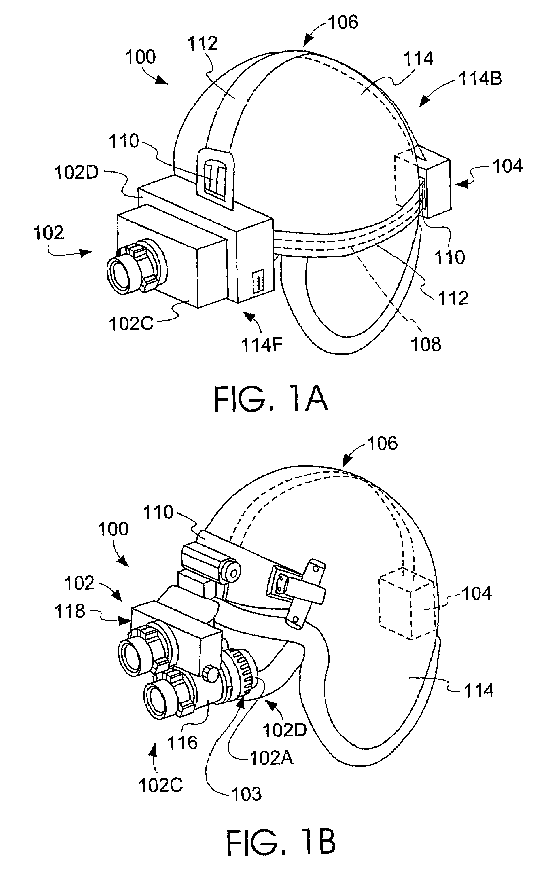
[0040]An optical device according to a first embodiment is illustrated in FIG. 1A. The infrared imaging system 100 comprises a sensor assembly 102, a power assembly 104, and an interconnect assembly 106. The sensor assembly 102 comprises a camera 102C and a display device 102D arranged as an integral unit. However, the camera 102C and the display device 102D need not be integral as more fully explained herein. The power assembly 104 supplies power to the sensor assembly 102, and may serve as a ...


PUM


Abstract

An infrared imaging device combines two sensors, each sensor sensitive to a different spectral range of infrared radiation. Both sensors are combined in a single camera sharing one of three common optical apertures, thus parallax is eliminated between the sensors. Further, a display device is aligned along an optical axis in common with the camera eliminating parallax between the display and camera. Images from the first sensor, the second sensor, or both sensors may be viewed optically and/or electronically. The device is handheld, or mountable on a headgear such as a helmet. When mounted on headgear, the display is viewable by directing the operator's gaze upward, thus the display does not interfere with an operator's straight and downward sight. The image can be sent to a remote display by a wireless transceiver, and waterproof, fireproof, vibration/impact resistance, and hot/cold weather resistance are achieved using a high strength plastic enclosure with foam insert.

Description

CROSS-REFERENCE TO RELATED APPLICATIONS[0001]This application claims the benefit of U.S. Provisional Application No. 60 / 224,189 filed Aug. 9, 2000, which is incorporated herein by reference.STATEMENT REGARDING FEDERALLY SPONSORED RESEARCH OR DEVELOPMENT[0002]This invention was made with government support under Contracts No. USZA22-00-P-0006 and No. USZA22-00-P-0029 awarded by U.S. Special Operations Forces. The Government has certain rights in this invention.BACKGROUND OF THE INVENTION[0003]The present invention relates in general to an infrared sensor device and in particular to a handheld or headgear mountable infrared sensor device capable of displaying fused or mixed radiation from infrared and other spectral sensors.[0004]As is well known, light absorption properties of the atmosphere define several frequency bands that are favorable to the transmission of light without undue absorption. Some of these frequency bands define spectral ranges that provide useful information for a...

Claims


Application Information

Patent Timeline
Patent Type & Authority Patents(United States)
IPC IPC(8): G01J5/00G02B23/12H04N5/33
CPCG02B23/125G02B27/1066H04N5/33
Inventor ZHANG, EVAN Y. W.
Owner ZHANG EVAN
Why Eureka
Try Eureka