
Dual-voltage wordline drive circuit with two stage discharge

a driver circuit and dual-voltage technology, applied in the field of memory devices, can solve the problems of large current spike on a vpp supply, negative impact on data retention time, and increase the sub-threshold leakage of the transfer device, and achieve the effect of suppressing the sub-threshold leakage and efficient charge transfer

Active Publication Date: 2008-03-18
RAMBUS INC
View PDF20 Cites 31 Cited by
  • Summary
  • Abstract
  • Description
  • Claims
  • Application Information

AI Technical Summary

Benefits of technology

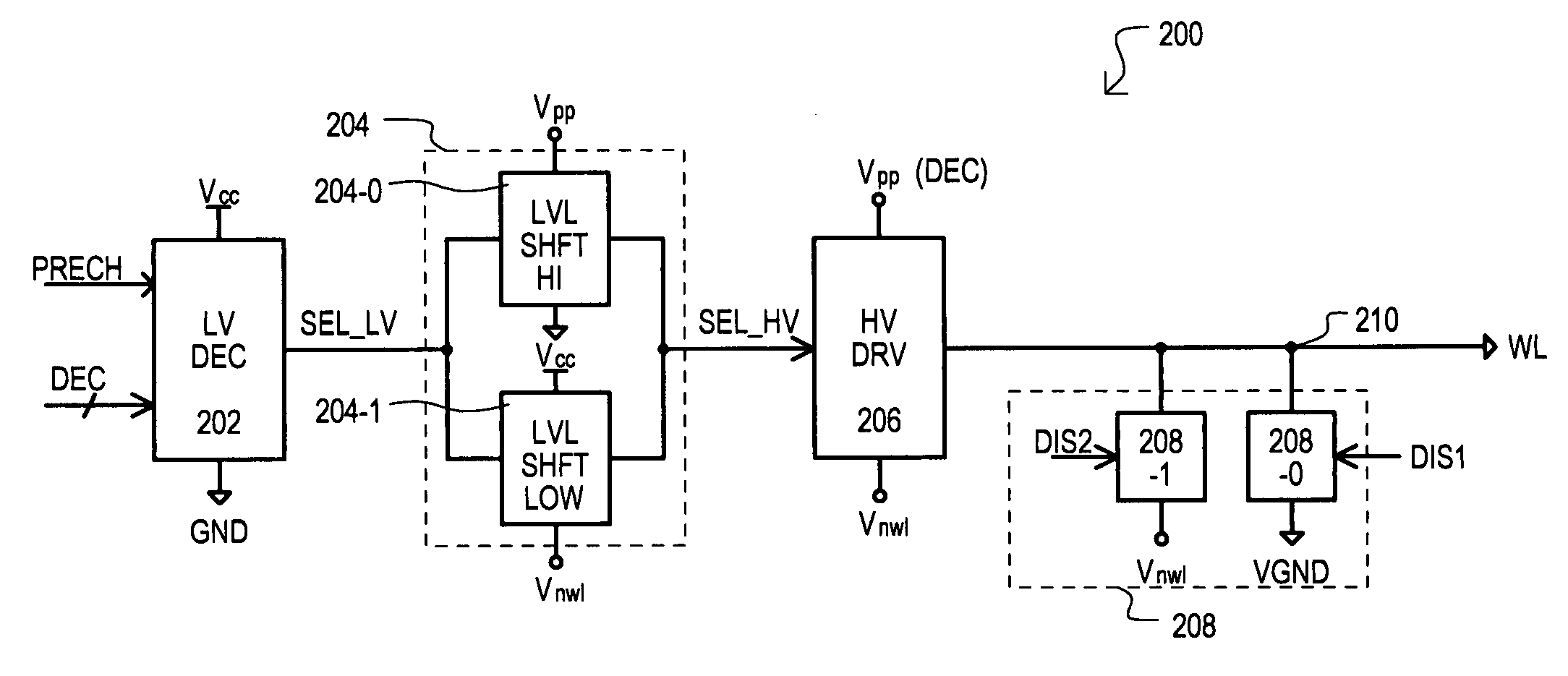
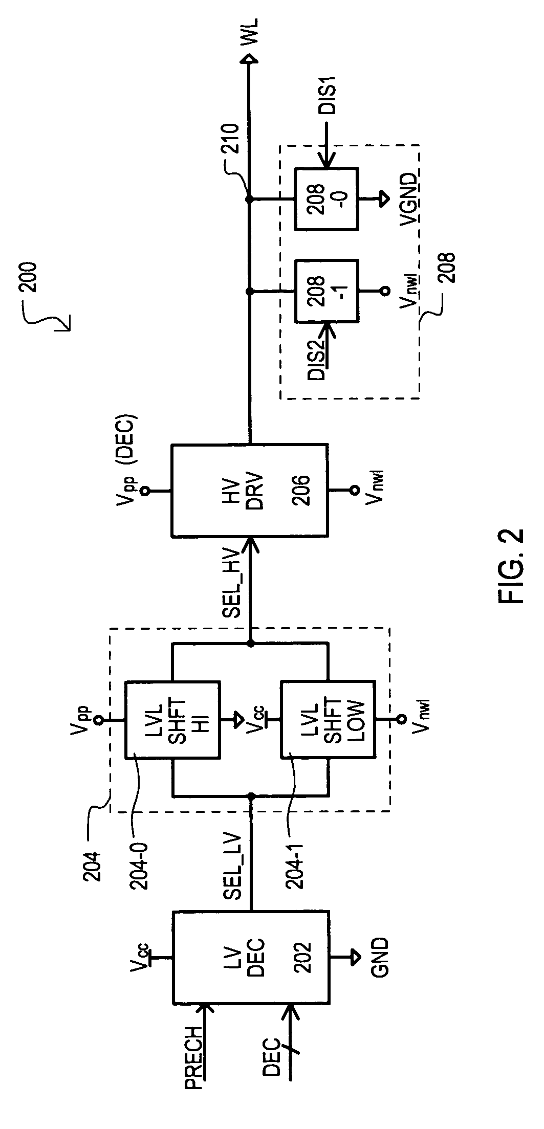
[0020]In this way, level shifting can be performed in a wordline by wordline basis, enabling decoding operations for wordline selection, particularly dynamic decoding, to occur at a lower voltage. This can reduce current spikes on a boosted voltage supplies as compared to conventional approaches that decode based on boosted voltage levels.
[0027]In this way, a boosted high voltage can enable efficient transfer of charge from such memory cells, while a boosted low voltage can enable the suppression of sub-threshold leakage in such cells.
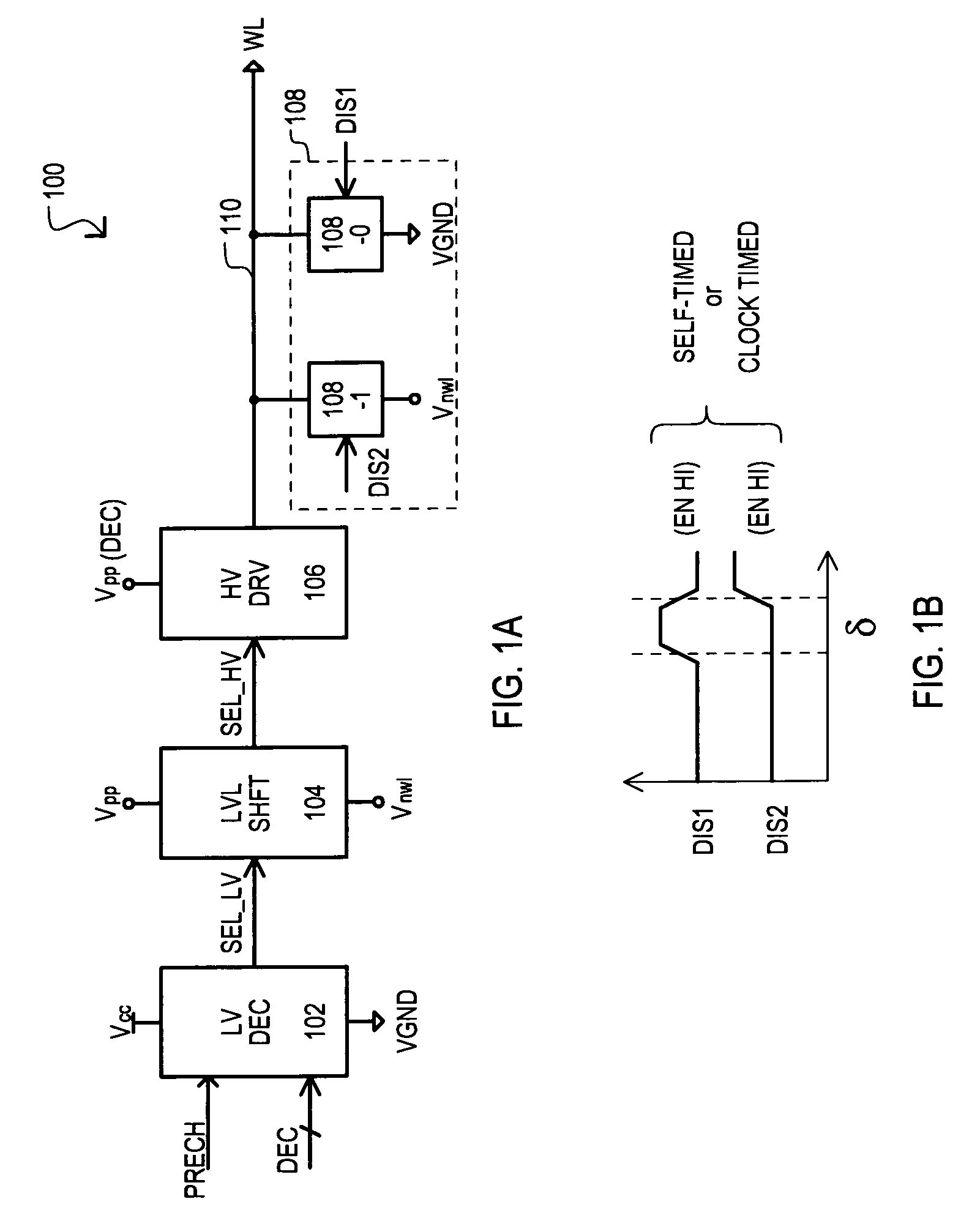
[0029]In this way, wordlines can be discharged in a two-stage operation. Such an arrangement can advantageously reduce current spikes in the boosted low voltage supply by first discharging wordline charge to a supply level.
[0031]In this way, a first discharge path can include a second discharge transistor having a “diode” connection with respect to the wordline. The current path of the second transistor can be enabled by a first transistor that is turned on when the wordline is deselected. Such an arrangement can result in a self-timed discharge operation, which can result in the need for fewer control signals and / or a more compact circuit design.
[0037]In this way, two-stage wordline discharge can be timed according to an external clock signal. Such an arrangement may be advantageously implemented in a synchronous memory device.
[0038]The present invention can also include a method of reducing current consumption in a memory device having a plurality of wordlines. The method can include selecting a wordline by coupling the selected wordline to a boosted high voltage, and de-selecting the wordline by coupling the selected wordline to a low voltage. Subsequently, the selected wordline can be coupled to a boosted low voltage that is lower in potential than the low voltage.

Problems solved by technology

However, such an arrangement can increase a sub-threshold leakage of a transfer device.
Increased sub-threshold leakage can deplete charge from the storage capacitor of a DRAM cell and hence negatively impacts data retention time.
As a result, when multiple wordline drivers are cycled to a precharge state (signal PRECH low), multiple nodes ND1 are driven to boosted high voltage Vpp, which can cause a large current spike on a Vpp supply.
Further, as a wordline is discharged to a boosted low (Vnwl) level, a significant current spike for such a supply can be created.
This can cause sub-threshold leakage in transfer devices that should otherwise be maintained in the fully off state.

Method used


Image

  • Dual-voltage wordline drive circuit with two stage discharge
  • Dual-voltage wordline drive circuit with two stage discharge
  • Dual-voltage wordline drive circuit with two stage discharge

Examples


Embodiment Construction

[0059]The various embodiments of the present invention are directed to an architecture and / or circuit for a wordline driver in a memory device, such as a dynamic random access memory (DRAM). For purposes of clarity, many of the details of RAMs and wordline drivers that are widely known and are not relevant to the present invention have been omitted from the following description.

[0060]Referring now to FIG. 1A, a wordline driver circuit according to a first embodiment is set forth in a block schematic diagram and designated by the general reference character 100. A wordline driver circuit 100 can be repeated in a memory device having volatile memory cells, such as DRAM cells, to form a memory device architecture. The wordline driver circuit 100 can include a low voltage decoder 102, a level shift circuit 104, a high voltage driver 106, and a two stage discharge circuit 108.

[0061]A low voltage decoder 102 can receive a first high voltage (Vcc) and a first low voltage VGND. In response...


PUM


Abstract

A wordline driver circuit can include single stage level shifters to translate a low voltage level (VGND to Vcc) to a high voltage level (Vnwl to Vpp). A wordline driver can further include a two-stage discharge circuit to pull down a wordline from a boosted high voltage Vpp to a boosted low voltage Vnwl. A two-stage discharge circuit can include (i) a first discharge path that can pull the wordline toward a first low voltage VGND; and (ii) a second discharge path that can pull the wordline toward a lower boosted low voltage Vnwl. Initially discharging a wordline to a first low voltage can reduce the amount of charge injected into a boosted low voltage Vnwl supply. A two-stage discharge circuit can be self timed or externally timed.

Description

[0001]This application claims the benefit of U.S. Provisional Patent Application Ser. No. 60 / 613,174, filed on Sep. 24, 2004.TECHNICAL FIELD[0002]The present invention relates generally to memory devices, and more particularly to dual voltage word line driver circuits for memory device, such as dynamic random access memories (RAMs) and methods for operating the same.BACKGROUND OF THE INVENTION[0003]Random access memory (RAM) devices, such as dynamic RAMs (DRAMs), typically include a memory array of DRAM cells accessed via wordlines (e.g., in a row direction) and bit lines (e.g., in column direction). A typical DRAM cell includes a pass transistor and a storage capacitor. In a read operation, the pass transistor (e.g., transfer device) is turned on according the voltage of a wordline to enable the transfer (i.e., sharing) of charge on a corresponding bit line. For high performance and / or compact array design, a pass transistor is typically an n-channel insulated gate field effect tra...

Claims


Application Information

Patent Timeline
IPC IPC(8): G11C8/00
CPCG11C8/08G11C11/4085
Inventor CHAPMAN, DAVIDARORA, ANUPAMMA, LINPARENT, RICHARD
Owner RAMBUS INC
Learn More