Method and device system for removing material or for working material

a technology of a working material and a method is applied in the field of a method and a system for removing material or tissue and treating material or tissue, which can solve the problems of increasing the complexity of the device, not allowing the user who manually treats hard tissue to detect, and increasing the cost of the devi

Inactive Publication Date: 2008-03-18
ALL OF INNOVATION MBH
View PDF23 Cites 179 Cited by
  • Summary
  • Abstract
  • Description
  • Claims
  • Application Information

AI Technical Summary

Benefits of technology

[0058]According to another advantage of the invention, conventional handpieces can be employed in the navigation system, wherein the handpiece has at least one opening for later attachment to a marker support and the opening is formed so as to be in formfitting engagement without play with a projection on the marker support when the handpiece and marker support are installed. Alternatively, the handpiece can have at least one projection for later attachment of a marker support, wherein the projection is formed so as to be in formfitting engagement without play with an opening of the marker support when the handpiece and marker support are installed.
, conventional handpieces can be employed in the navigation system, wherein the handpiece has at least one opening for later attachment to a marker support and the opening is formed so as to be in formfitting engagement without play with a projection on the marker support when the handpiece and marker support are installed. Alternatively, the handpiece can have at least one projection for later attachment of a marker support, wherein the projection is formed so as to be in formfitting engagement without play with an opening of the marker support when the handpiece and marker support are installed.

Problems solved by technology

Non-tactile tissue-removing effectors, such as laser beams, don't allow a user who manually treats hard tissue to detect by feel the shape of the removed tissue or the generated fitted shape.
Robot-controlled, tele-manipulated or interactively robot-guided instrument inserts always significantly increase the complexity of the device which adds to its cost.
In addition, the attending medical personnel as well as the nursing staff must have a high level of training and motivation, requiring significant expenses for training and installation.
In dentistry, adjoining structures are frequently accidentally injured with a tissue-removing sensor and / or instrument.
Even with navigation support, it is not always possible to cleanly shape a cavity.
Prefabricated implants cannot be cleanly fitted.
It is not possible to prefabricate inlays, onlays or bridges for a later fit.
It is not possible to prefabricate a supra-construction so that it later fits perfectly.
It is not possible to use high-quality standard inlays, onlays or bridges which are produced by a manufacturer of implants or similar manufacturers.
It is not possible to cleanly reshape cavities so that they meet certain medical criteria (e.g., distance from bacteria-infected, tumorous tissue).
It is not possible to cleanly reshape cavities so that they meet certain manufacturing criteria (e.g., shaping of the fitted piece for fabrication with three-axes cutters).
It is not possible to cleanly reshape cavities so that they meet certain criteria for the integration of fitted pieces (insertion, plug-in, secured against rotation).
It is not possible to cleanly reshape cavities so that they meet a combination of these criteria.
It is not possible to measure and store manually removed tissue (e.g., on a model), and to use the removed tissue as a “template” for a tissue removal with identical shape on the same or on another object (e.g., a patient's tissue).
In knee endoprosthesis, multiple cuts cannot be produced without fixing or kinematic guiding with cleanly defined cut surfaces.
In spinal surgery, decompressions and pedicle screw insertion cannot be performed without fixing the tissue and / or kinematically guiding the instruments.
Another disadvantage of conventional solutions is that the navigation systems according to the state of the art cannot use tools whose transformation matrix is not known ahead of time.
This limits the user to a tool set from a particular company.
The user is unable to calibrate a new tool without problems.
If the tools of an instrument, such as for example a handpiece, are changed, there is a risk that an unregistered tool is being used.
This can results in injury to the patient, since the position and angle values can be in error without being recognized as erroneous.
However, due to its concept and operating mode, the system cannot be used as a treatment system.
This machine, however, is not used with patients and is unable to later compensate for undercuts of the cavities on the patient.
These methods have a significant disadvantage in that the drill template is difficult to affix on the mucous membrane of the mouth and a template for guiding the handpiece is placed exactly at the location where drilling occurs.
The method can also not be used for producing cavities of arbitrary shape.
It is not possible to remove tissue with particular geometric characteristics.
The present state of the art offers no possibilities to provide the handpieces of the dentist at a later time with a marker when only small modifications are made, so that the handpieces can be easily used with a navigation system.
Special handpieces exist for this application, which however have to be acquired by the dentist at a substantial cost.
They cannot be used with normal turbines and the handpiece cannot be easily separated from the turbine.

Method used


Image

  • Method and device system for removing material or for working material
  • Method and device system for removing material or for working material
  • Method and device system for removing material or for working material

Examples


Embodiment Construction

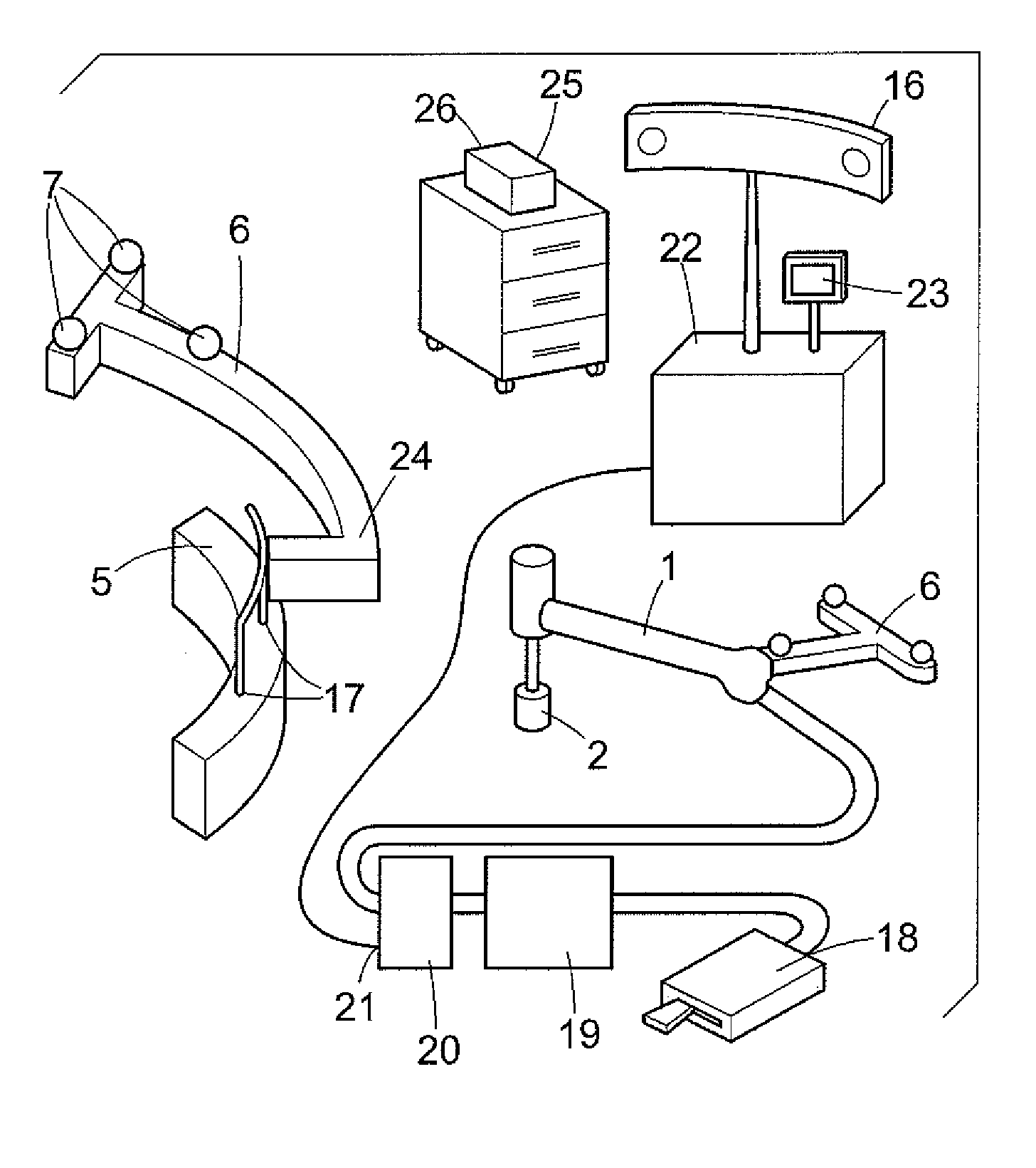
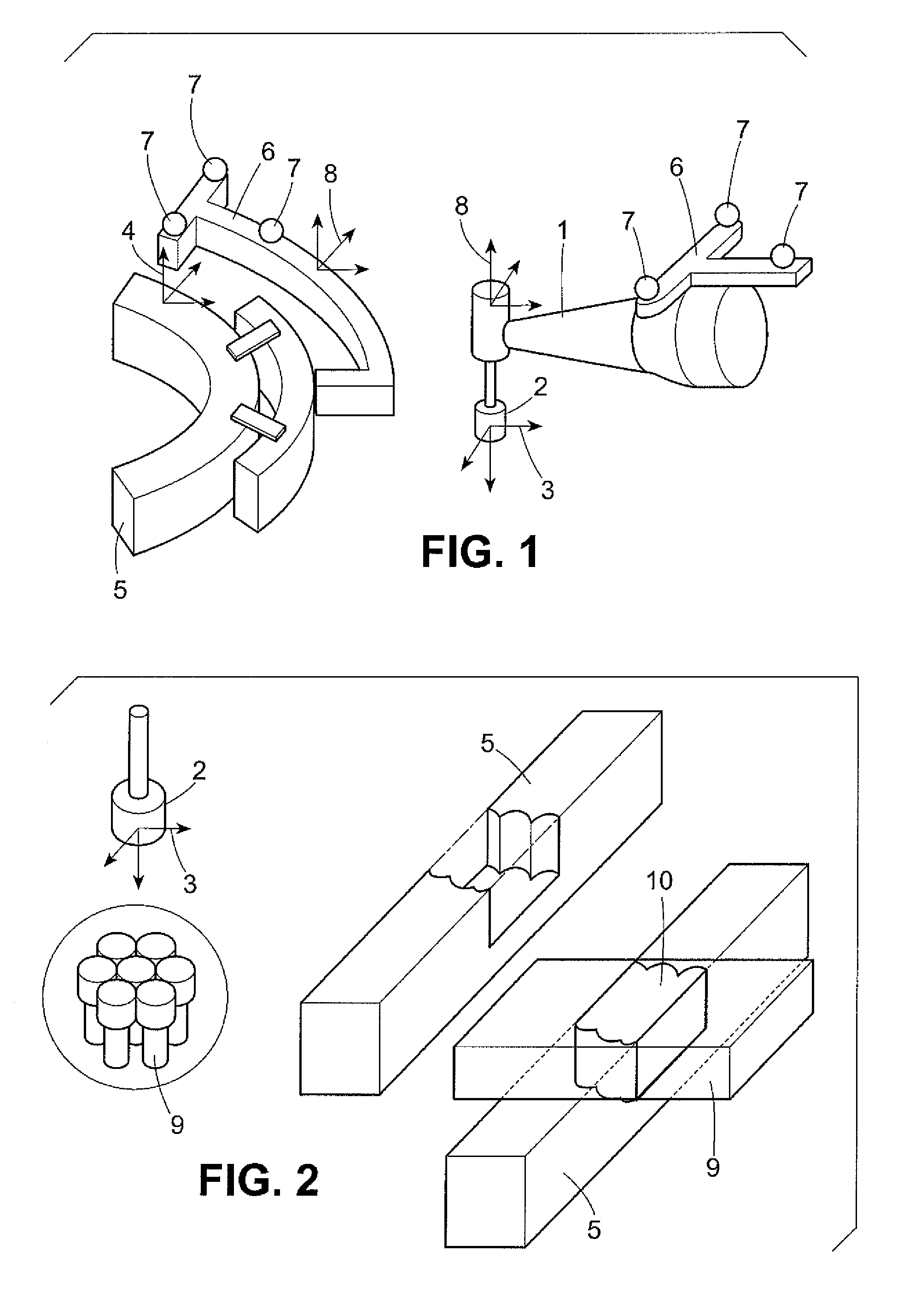
[0074]FIG. 1 shows the handpiece of a medical instrument with a tissue-removing effector 2 in a measurable effector position (position and orientation) 3 relative to a reference position 4 of a tissue object 5. The tissue-removing geometry of the effector 2 is known to be almost unchangeable (e.g., cutters, drills) or can be measured and / or adjusted (e.g., laser). The power for removing the tissue can be at least switched on and off, or preferably controlled. The effector 2 can be implemented as a saw blade, a drill, a cutter, a water or particle beam, a laser beam, ultrasound, or as another type of effector for removing tissue. The relative position T_EFF of the tissue-removing effector 3 relative to the reference position 4 T_OBJ of the tissue object 5 can be determined, for example, by a coordinate measurement method based on artificial or anatomic measurement markers located at a known position. FIG. 1 shows marker supports 6 which are secured in a fixed position relative to the...


PUM


Abstract

Method and system, for which can be used in the fields of medicine and dentistry as well as for the most varied types of material working in different areas of application and model working, provides that an exact removal of material or a highly precise, reproducible material working can be realized by acquiring, storing and processing data pertaining to position and / or orientation of an effector and their changes relative to the position of at least one reference body. The effector is controlled and / or regulated with regard to its power and / or parameterization based on a predetermined working volume, material volume removed and remaining material volume. A first marking support with markings is arranged on a handpiece with the effector, where the handpiece is connected to a control unit, and a second marking support with markings is attached to the material object or tissue object.

Description

FIELD OF THE INVENTION[0001]The invention relates to a method and system for removing material or tissue and for treating material or tissue and can be applied in medicine and dentistry as well as for different types of material processing and model working.[0002]The methods of the invention and the system can be applied, for example, to controllably arrange and guide handpieces as well as to switch on and off, to control power to or parameterize the effector in surgery and dentistry for optimally removing tissue in preparation for conservation and for the insertion of implants, inlays and onlays. In addition, high-precision cuts can be set up.BACKGROUND OF THE INVENTION[0003]Currently, instruments such as drills, cutters and saws, which are inserted in the chuck of a medical handpiece, are mostly used in medicine for removing tissue. Sometimes, laser systems are used which can separate and / or remove soft and hard tissue.[0004]In tissue removal, tissue cuts, tissue openings and tiss...

Claims


Application Information

Patent Timeline
Patent Type & Authority Patents(United States)
IPC IPC(8): G06F19/00A61B5/05A61C1/00A61B18/20A61B19/00A61C1/08A61C1/12A61C1/18A61C13/00A61C19/04G05B19/401
CPCA61B19/52A61B19/5244A61C1/082A61C13/0004G05B19/4015A61B18/20A61B2019/505A61B2019/5255A61B2019/5268A61B2019/5272A61B2019/5483A61C1/18G05B2219/33008G05B2219/37008G05B2219/37074G05B2219/37227G05B2219/37236G05B2219/40557G05B2219/40613G05B2219/45117G05B2219/45165G05B2219/45167G05B2219/49007G05B2219/49353Y10S128/92A61B2090/3983A61B90/36A61B2034/2055A61B2034/2068A61B2034/2072A61B34/20A61B2034/105
Inventor LUTH, TIMBIER, JURGENBIER, ANGELIKAHEIN, ANDREASSCHERMEIER, OLAF
Owner ALL OF INNOVATION MBH
Why Eureka
Try Eureka