Densifier for simultaneous conditioning of two cryogenic liquids

a densifier and cryogenic liquid technology, applied in the direction of machines/engines, lighting and heating apparatus, container discharging methods, etc., can solve the problems of reducing the take-off weight and payload capacity, reducing the requirements of pressurizing gas, and affecting the current apparatus and techniques for densifying cryogenic propellants

Inactive Publication Date: 2008-03-25
SIERRA LOBO
View PDF51 Cites 22 Cited by
  • Summary
  • Abstract
  • Description
  • Claims
  • Application Information

AI Technical Summary

Problems solved by technology

First, increased propellant density translates into smaller propellant tanks which result in lower take-off weight and larger payload capacities.
In addition, lower operating pressures for expendable launch vehicles result in lower pressurizing gas requirements.
Current apparatus and techniques for densifying cryogenic propellants suffer from a number of drawbacks, principal among which is that most require moving parts operating at cryogenic temperatures.
According to this method a mechanical machine having moving parts (the compressor) must operate adjacent to or in contact with cryogenic materials likely to cause machine failure.
The test program was cancelled primarily due to failure of the compressor.
Testing of the X-33 oxygen densifier has shown the cold gas compression units to be highly unstable, un-repeatable, and unreliable during operation for long periods of time; i.e. the time required to load a launch vehicle.
In fact, one of the compressor stages of the X-33 oxygen densifier has failed causing destructive damage to the impeller and impeller housing.
A heat exchanger is used to warm the evacuated vapor prior to entering the vacuum pumps because the pumps cannot handle cold vapors.
However, they too require rotating machinery operating at cryogenic temperatures.
Major disadvantages of the above densification methods are poor reliability and high operational and maintenance costs associated with rotating machinery and moving parts that operate at or near cryogenic temperatures.
A key disadvantage of evaporative cooling techniques is the generation of sub-atmospheric pressures inside hydrogen storage tanks.
This can lead to a potentially catastrophic situation in which air (oxygen) from the atmosphere is drawn into the hydrogen system through a leaky seal or a vent.

Method used


Image

  • Densifier for simultaneous conditioning of two cryogenic liquids
  • Densifier for simultaneous conditioning of two cryogenic liquids
  • Densifier for simultaneous conditioning of two cryogenic liquids

Examples


first embodiment

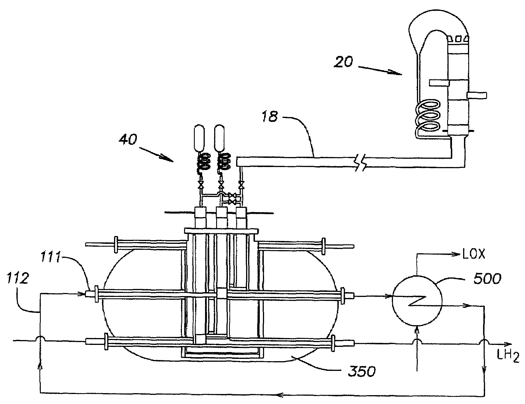
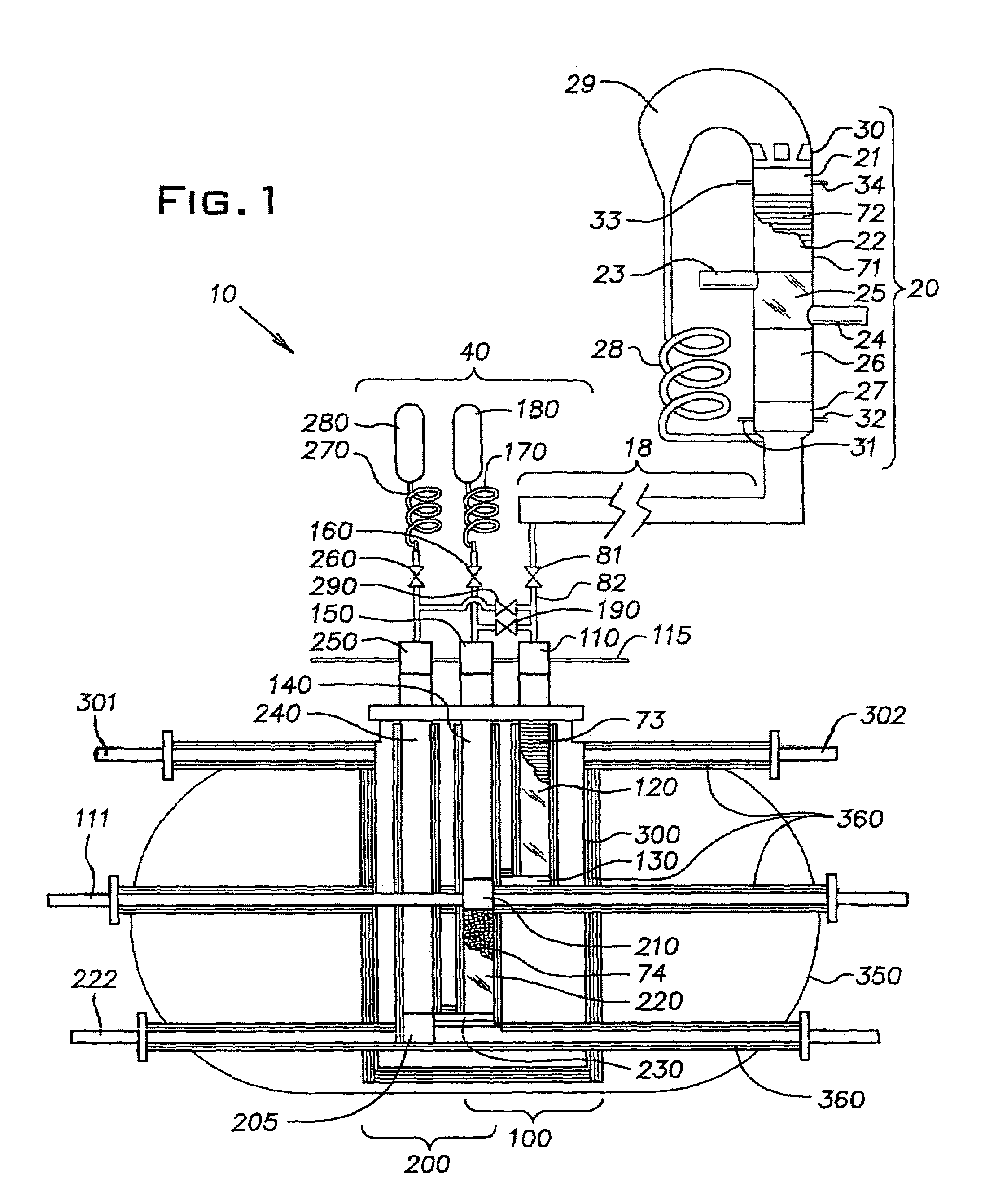
[0031] the densifier has three principal components; an oscillatory power source, a resonance tube 18, and a two-stage orifice pulse tube refrigerator (OPTR) 40. Referring to FIG. 1, a fully acoustic densifier 10 is shown having an acoustic heat engine as the oscillatory power source. By fully acoustic, it is meant that no mechanical energy input (and therefore no moving parts) are present or required in the densifier 10; oscillatory acoustical power generated by the acoustic heat engine provides the necessary power to the OPTR 40 for generating net refrigeration power therein. Preferably, the acoustic heat engine is a thermoacoustic prime mover 20 as shown in FIG. 1. The OPTR 40 utilizes acoustical power generated in the prime mover 20 to generate net refrigeration power to supercool cryogenic propellants such as liquid oxygen (LOX) and liquid hydrogen (LH2).

[0032]Preferably, the prime mover 20 is a Thermoacoustic Stirling Heat Engine (TASHE). TASHE heat engines are generally known...

second embodiment

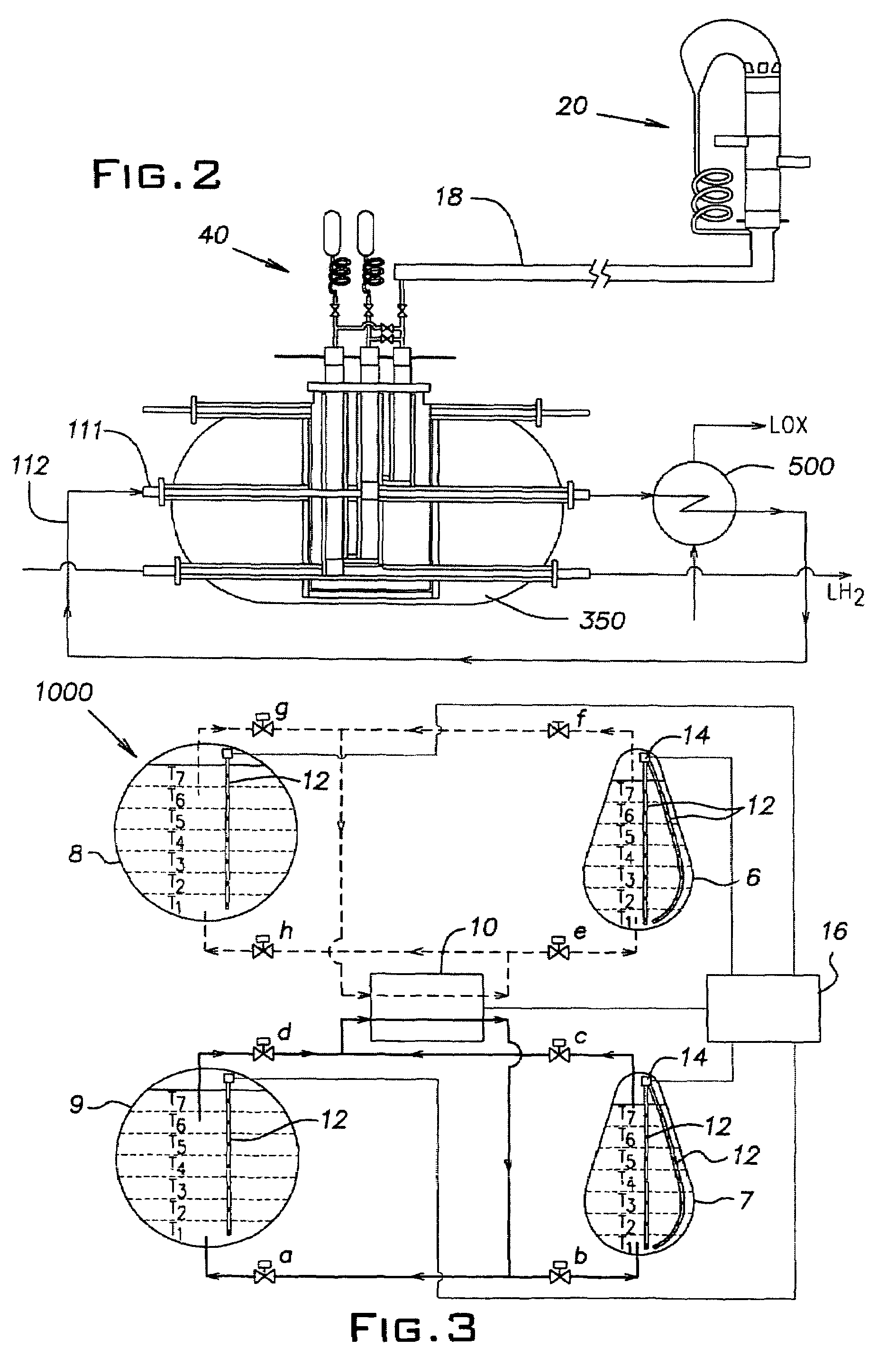
[0058]Referring to FIG. 2, a fully acoustic densifier 10 is shown as in FIG. 1, with a secondary heat exchanger 500 connected to the first cryogenic passage 111 via an inert recycle passage 112. In this embodiment, an inert cryogenic liquid, such as liquid nitrogen, flows through the inert recycle passage 112 (and first cryogenic passage 111), and is cooled by the common thermal block 210 in place of liquid oxygen. (LH2 is still densified in cold heat exchanger 205 as before). Cooled liquid nitrogen is subsequently fed into secondary heat exchanger 500 to separately densify liquid oxygen, some distance from the hydrogen stream flowing through the second cryogenic passage 222. It should be noted that this embodiment is less preferred because cooling efficiency for oxygen will be significantly lower due to heat leak to the cooled nitrogen stream prior to entering secondary heat exchanger 500. In addition, the normal melting point of liquid nitrogen is 63.14 K meaning that LOX cannot b...


PUM


Abstract

A densifier is provided which in one embodiment can simultaneously densify two cryogenic liquids at different temperatures. The densifier has an oscillatory power source for generating oscillatory power and a two stage pulse tube refrigerator. The oscillatory power source can be a thermoacoustic heat engine or a mechanical oscillatory power source such as a linear flexure bearing compressor. The first stage densifies a first cryogenic liquid to a first cryogenic temperature, and the second stage densifies a second cryogenic liquid to a second, lower cryogenic temperature. A densified propellant management system also is provided which has a densifier for simultaneously densifying two cryogenic liquids at different temperatures, and a cryogenic temperature probe for measuring the temperature gradient in a cryogenic liquid.

Description

[0001]This application is a continuation-in-part of U.S. patent application Ser. No. 10 / 466,379 filed Jul. 15, 2003 now U.S. Pat. No. 7,043,925, which is a 371 of PCT patent application No. PCT / US02 / 01527 filed Jan. 17, 2002, which claims the benefit of U.S. provisional patent application Ser. No. 60 / 262,178 filed Jan. 17, 2001.BACKGROUND OF THE INVENTION[0002]1. Field of the Invention[0003]The present invention relates to a densifier for the simultaneous conditioning and densification of two cryogenic liquids, and more particularly to a densifier for the simultaneous densification of two cryogenic propellants at different temperatures.[0004]2. Description of Related Art[0005]Aerospace vehicles and spacecraft such as the space shuttle burn hydrogen fuel in the presence of oxygen for propulsion. To achieve maximum energy density and minimum storage volume, the hydrogen and oxygen propellants are stored onboard the spacecraft as cryogenic liquids. To achieve even greater energy densit...

Claims


Application Information

Patent Timeline
Patent Type & Authority Patents(United States)
IPC IPC(8): F25B9/00F17C13/02F17C5/00F25B9/14
CPCF25B9/145F02G2243/54F25B9/10F25B2309/1403F25B2309/1411F25B2309/1423F25B2309/1424
Inventor HABERBUSCH, MARK STEVENCULLER, ADAM JOHN
Owner SIERRA LOBO
Why Eureka
Try Eureka