
Recording method and optical disk device

a recording method and optical disk technology, applied in the field of recording methods and optical disk devices, can solve the problems of increasing recording/reproducing speed, increasing noise, increasing natural vibration of the medium, etc., and achieve the effect of preventing data deterioration and high speed

Inactive Publication Date: 2008-03-25
HITACHI CONSUMER ELECTRONICS CORP +1
View PDF10 Cites 1 Cited by
  • Summary
  • Abstract
  • Description
  • Claims
  • Application Information

AI Technical Summary

Benefits of technology

[0025]Next, means for solving (Problem 2) will be described. As described above, if a high-power semiconductor laser is used for realizing high-speed recording and signals are read out in a wide band for realizing high-speed reproduction, influence by amplifier noise and laser noise increases and S / N ration in the reproduction signal is lowered. Here, it is thought to increase the reproduction power. In this case, because the amplitude of the reproduction signal becomes relatively large in comparison with the amplifier noise, the influence by the amplifier noise decreases and the S / N ratio is improved. Further, because the noise generated from the semiconductor laser is influenced by natural radiation light as a light quantity component that is not laser-oscillated in the laser cavity, if the reproduction power is increased, the laser noise is reduced and the S / N ratio in the reproduction signal is improved because the above influence decreases. On the other hand, if the reproduction power is too increased, the temperature of the recording film excessively rises in reproduction and the amorphous mark is crystallized to deteriorate the data quality. Conventionally, in the standards of DVD-RAM 2× speed, 3× speed, and 5× speed, the reproduction power Pr is fixed to 1 mW. In case of recording / reproducing within the range from 6× speed to 16× speed, the value of the reproduction power Pr2 for improving the S / N ratio in the reproduction signal within a range in which the data quality is not deteriorated is determined by the medium maker. If the Pr2 value is recorded in the control data, by the drive device reading out that value and using it upon reproduction at 6× speed or more, the S / N ratio in the reproduction signal can be improved without deteriorating the data quality.
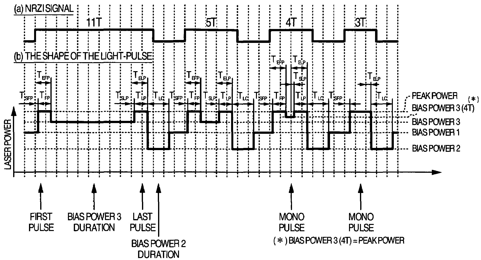
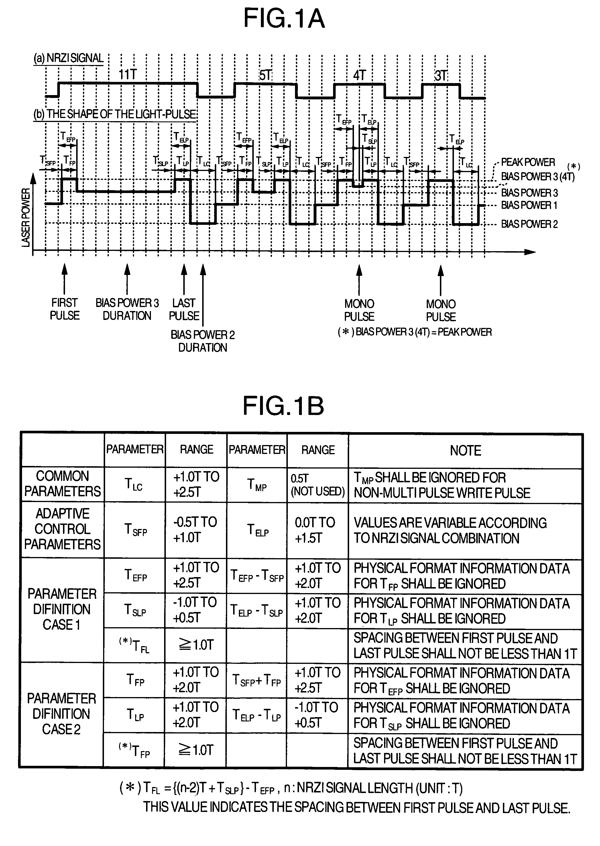
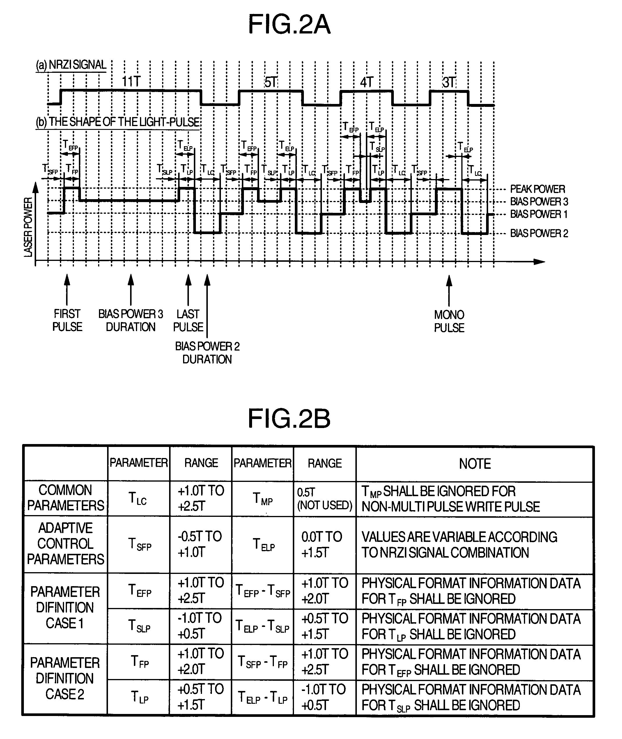
[0028]FIG. 5 shows experimental results showing jitters of first-time record data from 6× speed to 16× speed. Adjustment of recording conditions was performed at 6× speed and 16× speed, and as recording conditions of the speeds between them, those interpolated by (Equation 2) were used. Measurement of jitter values is carried out at 6× speed. When a conventional non-multi pulse is used, the cutoff phenomenon arises near 10× speed and the jitter value increases. On the other hand, when a mono pulse is used for recording the 4T mark, the jitter value becomes constant as about 5% irrespective of speed, and good recording performance was obtained.
[0038]Occurrence of the cutoff phenomenon of a laser driving circuit could be prevented and guarantee of compatibility of recording parameters and CAV recording could be realized. Further, S / N ratio upon reproduction at a high speed could be improved and deterioration of data could be prevented.

Problems solved by technology

At the present in which spread of recording type DVD drives has advanced, an increase in recording / reproducing speed is the most important technical development issue.
In general, in case of a DVD disk using a plastic base, the natural vibration of the medium increases as the rotational speed increases, and not only the noise increases, but also the medium is broken in the worst case.
In general, the laser noise increases as the power of the semiconductor laser increases.
Further, if the reproduction speed is increased, influence by amplifier noise and laser noise contained in a reproduction signal increases to correspond to the spread of band.

Method used


Image

  • Recording method and optical disk device
  • Recording method and optical disk device
  • Recording method and optical disk device

Examples


embodiment 1

Recording Method

[0062]Details of a recording method of the present invention is as described above. Here, experimental results using the recording method and details of a setup sequence will be described.

[0063]FIG. 15 shows experimental results showing dependency of overwrite jitter upon recording power when recording / reproducing are performed at 6× speed and 16× speed using a recording pulse of the present invention, respectively. As shown in the drawing, good jitter values of 9% or less could be obtained. The reproduction power was 1.5 mW.

[0064]FIG. 16 shows reproduction signals, jitter values, and bit error rates on the above experiment. The bit error rate was measured using a PRML (Partial Response Maximum Likelihood) method with the class being set at PR(3,4,4,3). Good bit error rates of 10−6 or less could be obtained.

[0065]FIG. 17 shows measurement results of jitter value and bit error rate when the recording speed and reproduction speed are changed. In case of 2× speed, the r...

embodiment 2

Optical Disk Device

[0071]FIG. 21 shows an embodiment showing a construction of an optical disk device of the present invention. An optical disk medium 100 is rotated by a motor 160. Upon reproduction, a laser power / pulse controller 120 controls current flowing in a semiconductor laser 112 within an optical head 110 so that optical intensity instructed by CPU 140 is obtained, to generate a laser light 114, and the laser light 114 is converged by an objective lens 111 to form an optical spot 101 on the optical disk medium 100. A reflected light 115 from the optical spot 101 is detected by a photo-detector 113 via the objective lens 111. The photo-detector 113 comprises a plurality of divided photo detective elements. A readout signal processor 130 used a signal detected by the optical head 110 to reproduce information recorded on the optical disk medium 100. Upon recording, the laser power / pulse controller 120 converts predetermined record data into predetermined recording pulse curre...


PUM

PropertyMeasurementUnit
reproduction poweraaaaaaaaaa
rotational speedaaaaaaaaaa

Abstract

In order that it is realized to put 16× speed DVD-RAM in practice, a recording method coping with CAV (constant angular velocity) and a method for improving S / N ratio are provided and an optical disk device using them is provided. In order that a cutoff phenomenon of pulse in a laser driving circuit may not occur, the shortest pulse width is set at 1 Tw or more where Tw indicates a window width, and a recording pulse in which a 4T mark is recorded with a mono pulse where T indicates a detection window width and the parameter setting range are prescribed. Simultaneously, a reproduction power for 6× speed or more is set at 1.5-2.0 mW, different from a conventional value, and a setup sequence with which deterioration of data in reproducing does not occur is provided. Thereby it becomes possible to put 16× speed DVD-RAM in practice.

Description

INCORPORATION BY REFERENCE[0001]The present application claims priority from Japanese application JP2004-184410 filed on Jun. 23, 2004, the content of which is hereby incorporated by reference into this application.BACKGROUND OF THE INVENTION[0002]The present invention relates to a recording method and an optical disk device, wherein a record mark different in physical properties from the other portion is formed on a record medium to record information, and particularly to a recording method for a DVD-RAM medium using a phase change optical recording material, and an optical disk device using it.[0003]As rewritable type DVD-RAM using a phase change optical material, those of 2× speed, 3× speed, and 5× speed have been standardized, and a super multi drive coping with those have been already produced. At the present in which spread of recording type DVD drives has advanced, an increase in recording / reproducing speed is the most important technical development issue. The present writer...

Claims


Application Information

Patent Timeline
Patent Type & Authority Patents(United States)
IPC IPC(8): G11B7/0045G11B5/09G11B7/00G11B7/125
CPCG11B7/0062G11B7/1263G11B7/1267G11B7/00456
Inventor MINEMURA, HIROYUKIWATANABE, KOICHI
Owner HITACHI CONSUMER ELECTRONICS CORP
Learn More