Receiving apparatus in OFDM transmission system

a transmission system and receiving apparatus technology, applied in the field of receiving apparatus in an orthogonal frequency division multiplexing (ofdm) transmission system, can solve the problems of reducing the ratio of peak-to-average power, reducing the performance of fading tracking, and increasing the symbol length

Inactive Publication Date: 2008-04-22
FUJITSU LTD
View PDF10 Cites 45 Cited by
  • Summary
  • Abstract
  • Description
  • Claims
  • Application Information

AI Technical Summary

Benefits of technology

[0023]Accordingly, an object of the present invention is to reduce ISI (intersymbol interference) and ICI (intercarrier interference) ascribable to a delayed wave that has exceeded a guard interval.

Problems solved by technology

On the other hand, adding on a GI symbol (a redundant symbol) causes a decline in transmission efficiency.
This gives rise to certain problems encountered in multicarrier transmission, namely an increase in the ratio of peak-to-average power (degradation of performances ascribable to non-linear distortion in an amplifier) and a decline in fading tracking performance due to enlarged symbol length, and the number of subcarriers is designed in a tradeoff among these factors.
However, the delay time of a delayed wave along an actual transmission path varies greatly, and the delay spread is large, especially outdoors, e.g., 0.2 to 2.0 μs in urban areas and 10 to 20 μs in mountainous areas.
The conceivable GI length usually cannot provide compensation for 100% of all service areas.
That is, the BER performance degrades.
Further, control is complicated with a multicarrier adaptive modulation system in which the modulation scheme is changed over subcarrier by subcarrier.
Thus, problems still remain with the conventional method, namely the fact that computation cost for attaining the objective is high (especially in a case where concurrent use is made of adaptive modulation), and the fact that encoding gain declines when concurrent use is made of FEC.

Method used


Image

  • Receiving apparatus in OFDM transmission system
  • Receiving apparatus in OFDM transmission system
  • Receiving apparatus in OFDM transmission system

Examples


first embodiment

(B) First Embodiment

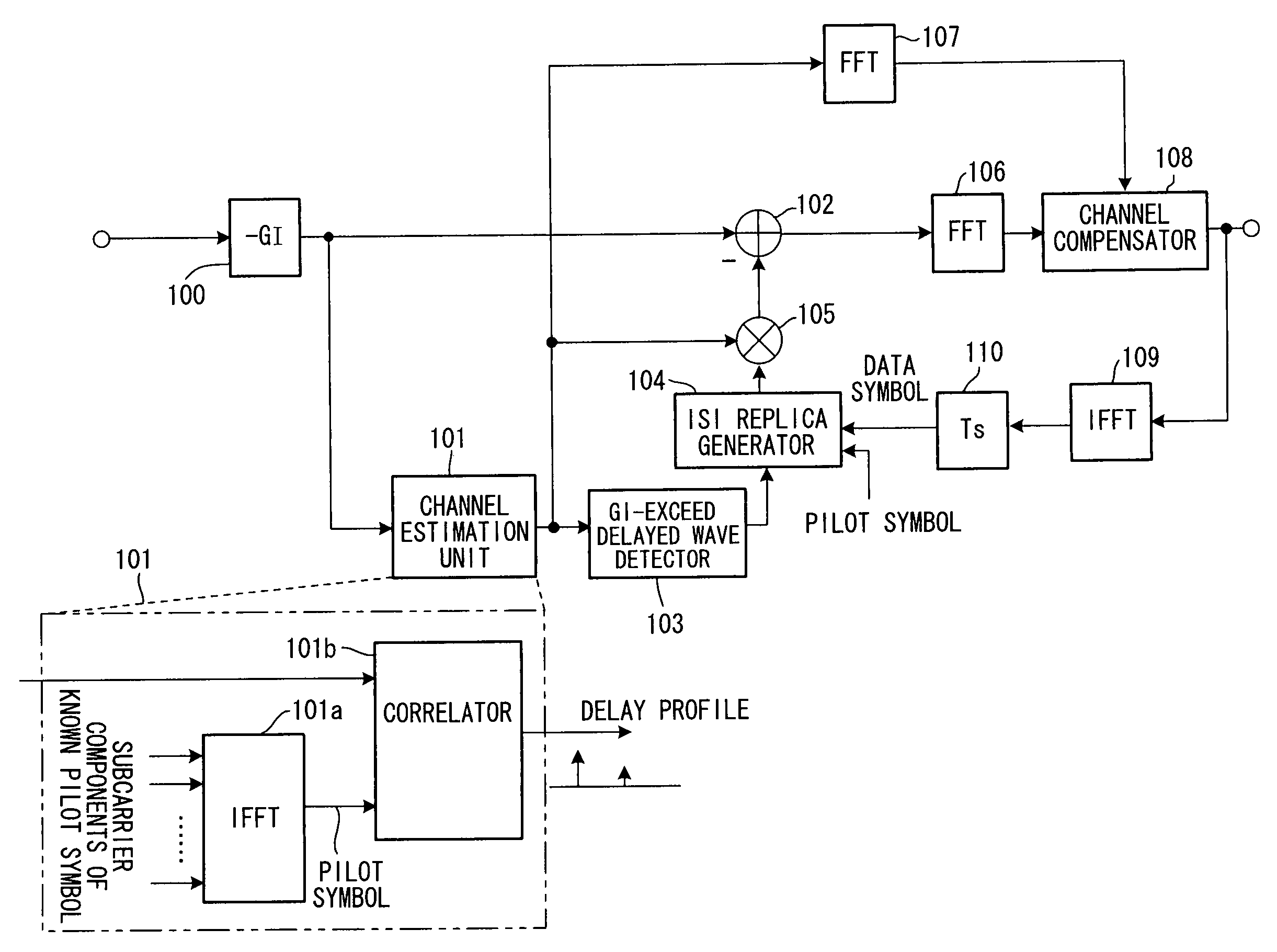
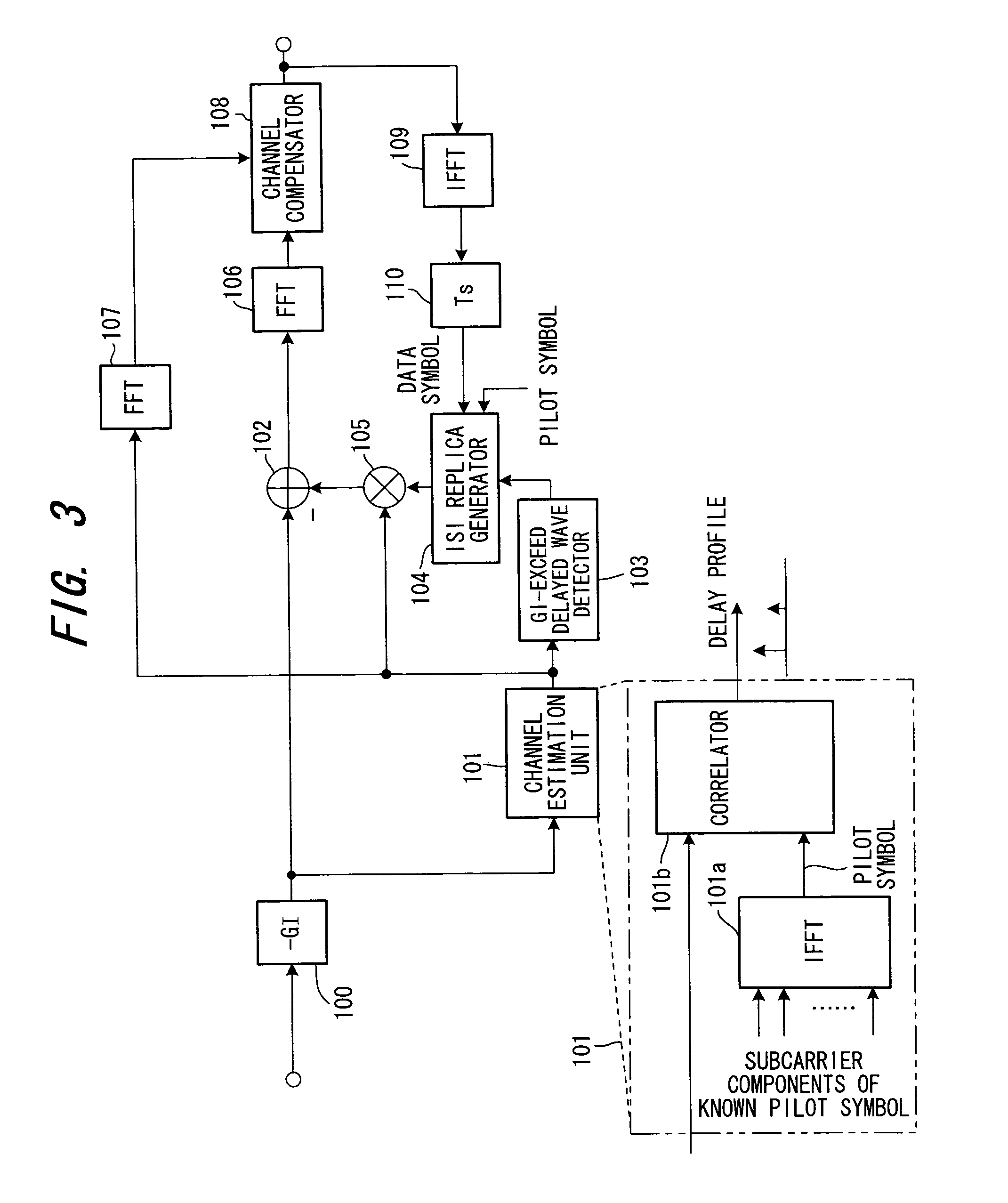
[0099]FIG. 3 is a block diagram illustrating a receiving apparatus in an OFDM transmission system according to a first embodiment of the present invention. In this embodiment and in the embodiments that follow it, signal processing in a time domain is executed before FFT processing, processing in a frequency domain is executed after FFT processing, and processing in the time domain is executed after IFFT processing. The first embodiment illustrates a case where channel estimation / measurement of delay profile using a receive signal (i.e., time waveform) prior to FFT processing on the receiving side is carried out.

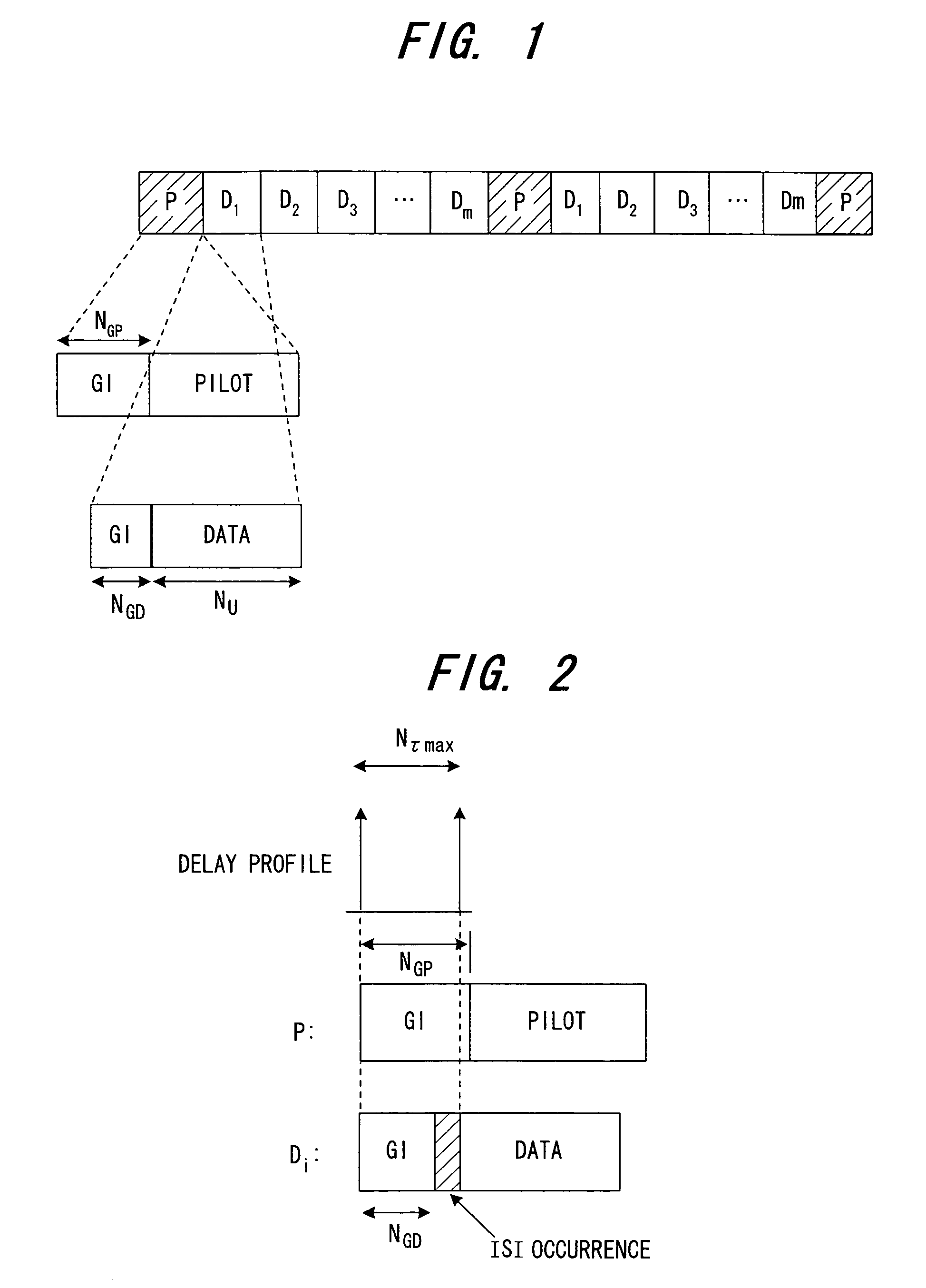
[0100]A receiving unit (see the radio receiver 11 and quadrature demodulator 12 in FIG. 54) inputs the receive signal to a guard-interval removal unit 100. It should be noted that the guard-interval length NGP added onto the pilot symbol P is greater than the guard-interval length NGD added onto the data symbol Di (NGP>NGD)

[0101]The guard-interval removal...

second embodiment

(C) Second Embodiment

[0115]FIG. 9 is a block diagram illustrating a receiving apparatus according to a second embodiment. Whereas the first embodiment suppresses only ISI, the second embodiment simultaneously suppresses ICI in addition to ISI.

[0116]FIGS. 10A to 10F are diagrams useful in describing the principle of ICI suppression. In the first embodiment, the receive signal shown in FIG. 10B is subjected to FFT processing upon eliminating the the ISI segment y of the delayed wave B shown in FIG. 10A in order to remove ISI.

[0117]However, the delayed wave B is discontinuous at the portion corresponding to the ISI segment y and, moreover, is not a periodic waveform. As a consequence, each subcarrier component obtained by FFT processing includes distortion ascribable to ICI. In order to eliminate such ICI, it will suffice to insert a waveform that will make the delayed wave B smooth over the span of the ISI segment y and periodic as well, as indicated by the dashed line in FIG. 10C.

[01...

third embodiment

(D) Third Embodiment

[0125]The second embodiment suppresses ISI and ICI simultaneously. That is, as shown in FIG. 10D, the receive signal of FIG. 10B is subjected to FFT processing, after which a continuous-signal waveform is obtained, as shown in FIG. 10E, if IFFT processing is applied. The tail-end segment y of the continuous-waveform signal of FIG. 10E is cut out and inserted into the segment y at the front end of the receive delayed signal of FIG. 10B, thereby making the delayed wave B a continuous periodic waveform, as shown in FIG. 10F, then the signal of FIG. 10F is subjected to FFT processing to suppress ICI.

[0126]In the second embodiment, as set forth above, only the segment y at the front end of the delayed wave B is replaced with the replica signal; the ISI portion of the desired wave (direct wave) A is not replaced with a replica signal. The segment y at the front end of the desired wave (direct wave) A undergoes fading and picks up noise, as a result of which quality dec...


PUM


Abstract

A receiving apparatus in an OFDM transmission system includes a channel estimation unit (101) for measuring a delay profile of a delayed wave having a delay greater than a guard interval of data; a guard-interval-exceed delayed wave detector (103) for detecting, from the delay profile as an intersymbol interference (ISI) portion, a delay-time portion greater than the guard interval of the data; a ISI replica generator (104) for generating, as the ISI replica, a time-waveform portion of a known symbol conforming to the ISI portion, or a time-waveform portion of the preceding symbol; subtractor (102) for subtracting the ISI replica from a receive signal; and an FFT arithmetic unit (106) for demodulating data by applying FFT processing to the result of subtraction.

Description

BACKGROUND OF THE INVENTION[0001]This invention relates to a receiving apparatus in an Orthogonal Frequency Division Multiplexing (OFDM) transmission system for receiving a transmitted signal that is the result of adding a guard interval onto a signal obtained by IFFT (Inverse Fast Fourier Transform) processing and then transmitting the signal. More particularly, the invention relates to a receiving apparatus in an OFDM transmission system in which, even if a delayed wave in excess of the guard interval is generated, excellent reception can be performed by reducing interference between symbols and interference between carriers.[0002]Frequency-selective fading ascribable to a multipath environment occurs in wideband wireless communications. An effective method of dealing with this is multicarrier modulation, which divides the transmission bandwidth into narrow bands (subcarriers) that do not undergo frequency-selective fading, and transmits the subcarriers in parallel. At present, sp...

Claims


Application Information

Patent Timeline
Patent Type & Authority Patents(United States)
IPC IPC(8): H03D1/06H04J11/00H04L25/03H04L27/26
CPCH04L25/03146H04L27/2607H04L27/2613H04L2025/03414H04L27/26
Inventor YOSHIDA, MAKOTO
Owner FUJITSU LTD
Why Eureka
Try Eureka