Gas concentration flux measuring device

a technology of flux measurement and gas densitometer, which is applied in the direction of optical radiation measurement, instruments, spectrophotometry/monochromators, etc., can solve the problems of inability to meet the necessary conditions of flux measurement, measurement delay or dilution effect, and inability to respond to the measurement, etc., to eliminate the influence of solid particles, improve the effect of measurement stability

Inactive Publication Date: 2008-04-29
MITSUBISHI HEAVY IND LTD +1
View PDF12 Cites 24 Cited by
  • Summary
  • Abstract
  • Description
  • Claims
  • Application Information

AI Technical Summary

Benefits of technology

[0025]In order to solve the above-mentioned problems in the prior art, it is an object of the present invention to provide a gas flux measuring device that is appropriate for regional measurements of forest or the like, has no influence of concomitants, has a high responsiveness and is excellent in measuring stability.

Problems solved by technology

(1) The gas densitometer of the state of the art does not necessarily satisfy the necessary conditions of the flux measurements.
That is, in the closed path type gas densitometer 96 of the sampling method that is generally used, there is caused a measurement delay or dilution effect for a structural reason.
Hence, there is a problem in the responsiveness (response time).
Also, as the concomitants, such as H2O and solid particles, give influences, a pre-treatment (dehumidifying, dedusting) is always needed and this makes enhancement of the responsiveness (response time) difficult.
Also, there is a problem in the measuring stability for reason of the light source.
(2) Regional continuous gas concentration measurements are difficult.
Hence, by the prior art systems, measurements of 1 m or more or, for example, measurements of regional gas concentration changes of such size as 10 m, 100 m or 1 km are difficult.
Nevertheless, if a multiplicity of measuring devices are arranged, the existence itself of these devices becomes an obstacle that will change the state of the measuring region (concentration, flux or the like).
Thus, an accurate regional flux measurement will be impossible.

Method used


Image

  • Gas concentration flux measuring device
  • Gas concentration flux measuring device
  • Gas concentration flux measuring device

Examples


Embodiment Construction

[0073]Herebelow, the present invention will be described more concretely based on the embodiments with reference to the appended drawings.

Basic Construction of Gas Concentration Measurements

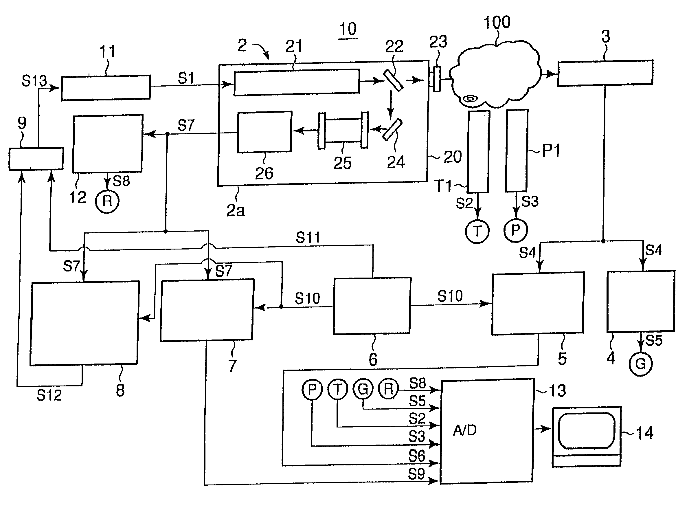
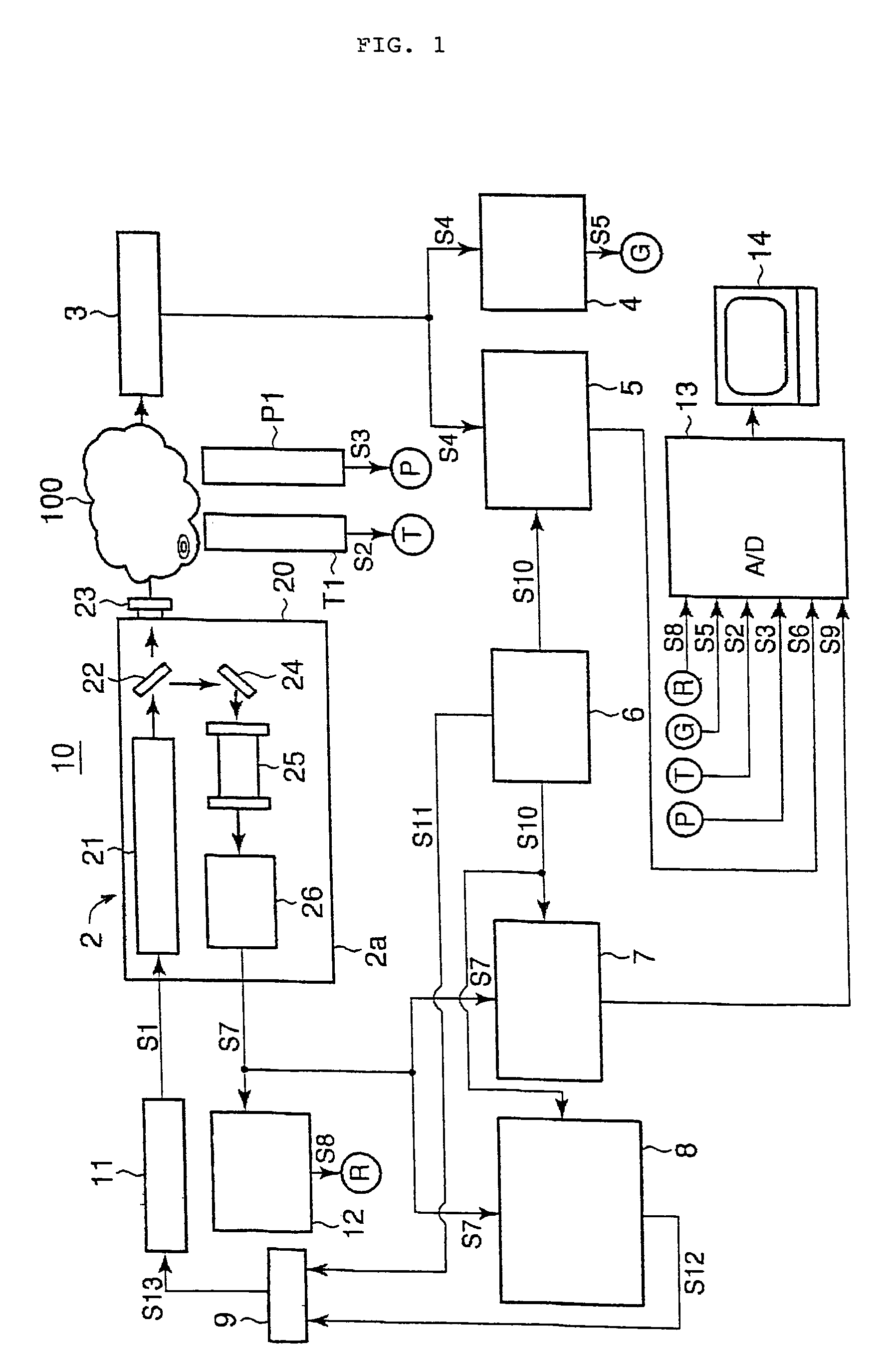
[0074]First, a basic construction of a gas concentration measuring device using the TDLAS to be used in the gas flux measuring device of the present invention will be described with reference to FIG. 1. In FIG. 1, a gas concentration measuring device 10 comprises a light source part 2, light receiver 3 for measuring purposes, direct current component detector 4 for measuring purposes, direct current component detector 12 for reference purposes, wavelength modulation demodulator 5 for concentration measuring purposes, wavelength modulation controller 6, wavelength modulation demodulator 7 for concentration calibrating purposes, wavelength modulation demodulator 8 for laser wavelength fixing signal purposes, adder 9, LD controller (laser output controller) 11, A / D converter 13 and computer 14 as an...


PUM

PropertyMeasurementUnit
lengthaaaaaaaaaa
sizeaaaaaaaaaa
sizeaaaaaaaaaa

Abstract

A gas flux measuring device measures a region, such as a forest, as a measuring object with no influence by concomitants and with high responsiveness and excellent measuring stability. The device includes a laser beam source, laser output controller, wavelength modulation controller, first light receiver, first direct current component detector, first wavelength modulation demodulator, optical system, reference cell, second light receiver, second direct current component detector, second wavelength modulation demodulator, third wavelength modulation demodulator, analyzer, adder, temperature measurement and pressure measurement. A flow velocity measuring device directly measures horizontal 2-directional flow velocity components and a vertical directional flow velocity component of a gas flow in the measuring region and puts out these measurement signals into the analyzer. Based on the signals inputted from the flow velocity measuring device, the analyzer makes an analysis based on the eddy correlation method and obtains, by calculation using this analysis result, a momentum flux and concentration of the measuring object gas.

Description

TECHNICAL FIELD[0001]The present invention relates to a gas flux measuring device used for such purposes as an assessment of CO2 absorption quantity by a forest, an investigation of the environment, such as an investigation of generation quantity of greenhouse gases (GHG) coming out of the ground, and a detection of gas leakage such as CO2 from underground disposal plants, gas storage facilities, pipelines, etc.BACKGROUND ART[0002]Recently, keen attention is being paid to the problem of global warming due to GHG, such as CO2, CH4, N2O or the like. To determine a discharge / leakage quantity of various GHG from the ground or industrial plants or to determine a CO2 absorption quantity by a forest is becoming more and more important.[0003]A most simplified method to determine the gas discharge (flux) quantity per unit area from the ground will be described with reference to FIG. 15A. In this method, a container 101 having a small hole 102 is placed so as to cover the ground 100a and a co...

Claims


Application Information

Patent Timeline
Patent Type & Authority Patents(United States)
IPC IPC(8): G01N15/06G01N21/49G01N21/85G01FG01N21/21G01N21/31G01N21/39G01W1/00
CPCG01J3/433G01N21/21G01N21/31G01N15/06
Inventor MUTA, KENJITANOURA, MASAZUMINAKAYA, KO
Owner MITSUBISHI HEAVY IND LTD
Why Eureka
Try Eureka