
Device for producing high frequency microwaves

a high-frequency microwave and microwave technology, applied in microwave heating, control electrodes, electric-emitting electrodes/cathodes, etc., can solve the problems of very low electromagnetic noise level of devices, achieve optimal design, reduce thermal deformation, and reduce sagging of gratings

Inactive Publication Date: 2008-04-29
KIST EURO KOREA INST OF SCI & TECH EURO FORSCHUNGSGMBH
View PDF12 Cites 1 Cited by
  • Summary
  • Abstract
  • Description
  • Claims
  • Application Information

AI Technical Summary

Benefits of technology

[0005]The object therefore underlying the invention is to produce a device for producing high-frequency microwaves, in which electrical short circuits, in particular between cathode and grating, due to thermal deformations, are extensively avoided.
[0007]By means of the precise positioning of at least the first grating arrangement and the cathode arrangement via positioning means and also the provision of a mounting for the cathode, which avoids the deformation of the cathode with reduction of the spacing between the grating arrangement and the cathode arrangement, a thermally stable arrangement is produced which permits small spacings between the cathode and the grating without short circuits.
[0008]The mounting comprises a cathode housing, on or in which the cathode is disposed as a part which is separate from the housing with a spacing from the housing wall, as a result of which deformation of the cathode arrangement because of different heat expansion coefficients between the heatable cathode and surrounding housing, is avoided. The mounting comprising the cathode housing holds the cathode if necessary by means of a cathode body whilst maintaining a gap between the parts. The gap serves as a buffer for the expansion due to heat.
[0009]The cathode housing insulates' the cathode from the input resonance cavity and is used for an arrangement of the cathode face and of the first grating in the micrometer range. It minimises a radial loss of heat energy from the cathode and reduces radial expansion of the cathode which could influence the dimension of the input resonance cavity.
[0011]The configuration of the cathode as a combination of a cathode body and metal plate emitting electrons minimises thermal deformation due to high operating temperatures.
[0013]Due to the above arrangement, an optimal design and an optimal arrangement of the components is ensured and thermal deformation, such as sagging of the gratings, is successfully reduced because of the bridges or web structure, short circuits between the components being avoided due to the clean spacing and alignment of the components relative to each other and as a result of which a good focusing of the electron beams is ensured.

Problems solved by technology

The electromagnetic noise level of the device is very low since the microwave energy is produced by a linear movement of the electrons.
However, the temperature of the cathode faces is in the range of 600° C. to 1,000° C. At such high temperatures, it is difficult because of the thermal deformations to maintain the precise alignment, which results in for example a contact between the grating and the cathode but also between the gratings themselves or between the grating and the anode.
This is a critical problem for operating the above-mentioned device.

Method used


Image

  • Device for producing high frequency microwaves
  • Device for producing high frequency microwaves
  • Device for producing high frequency microwaves

Examples


Embodiment Construction

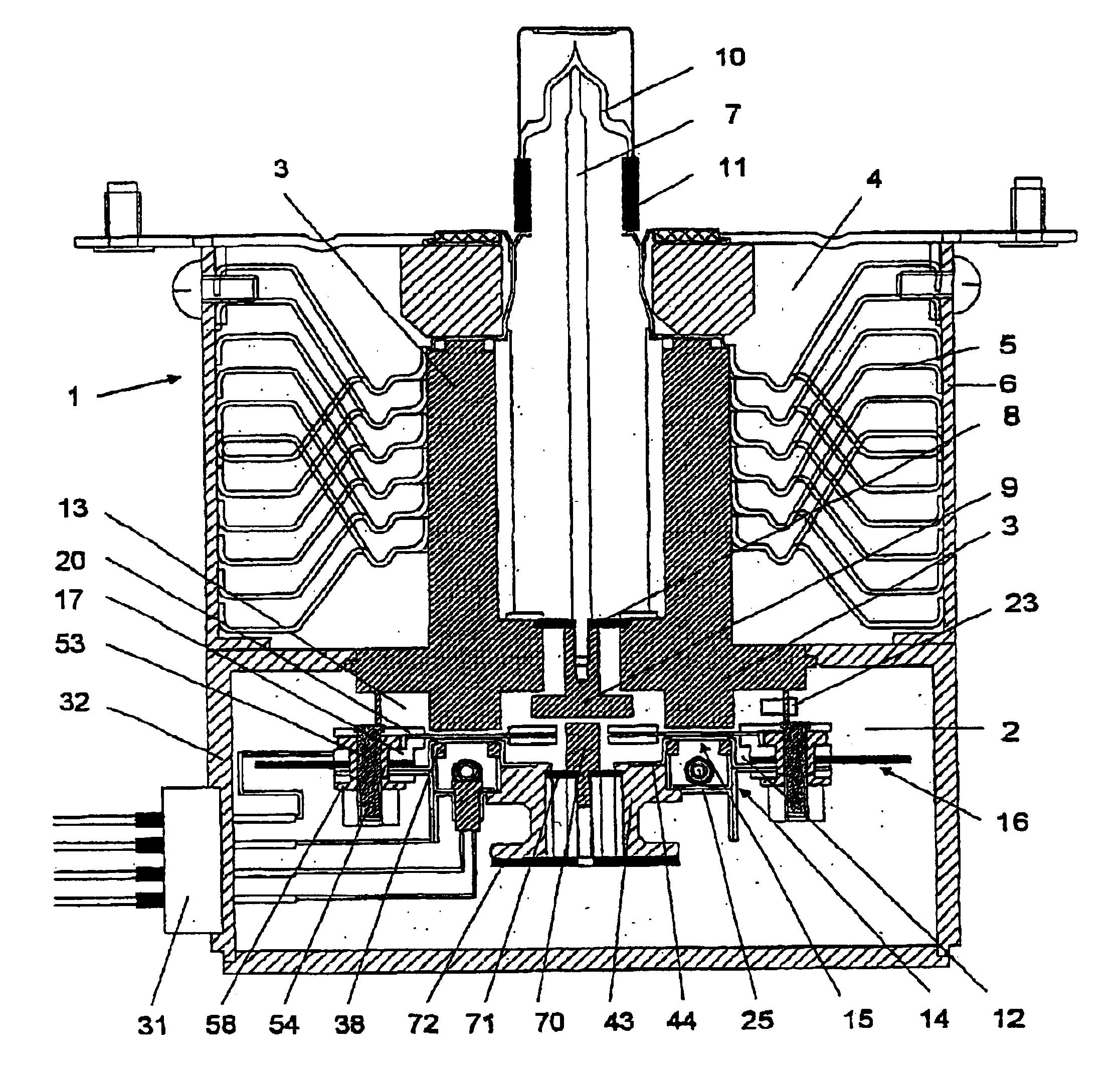
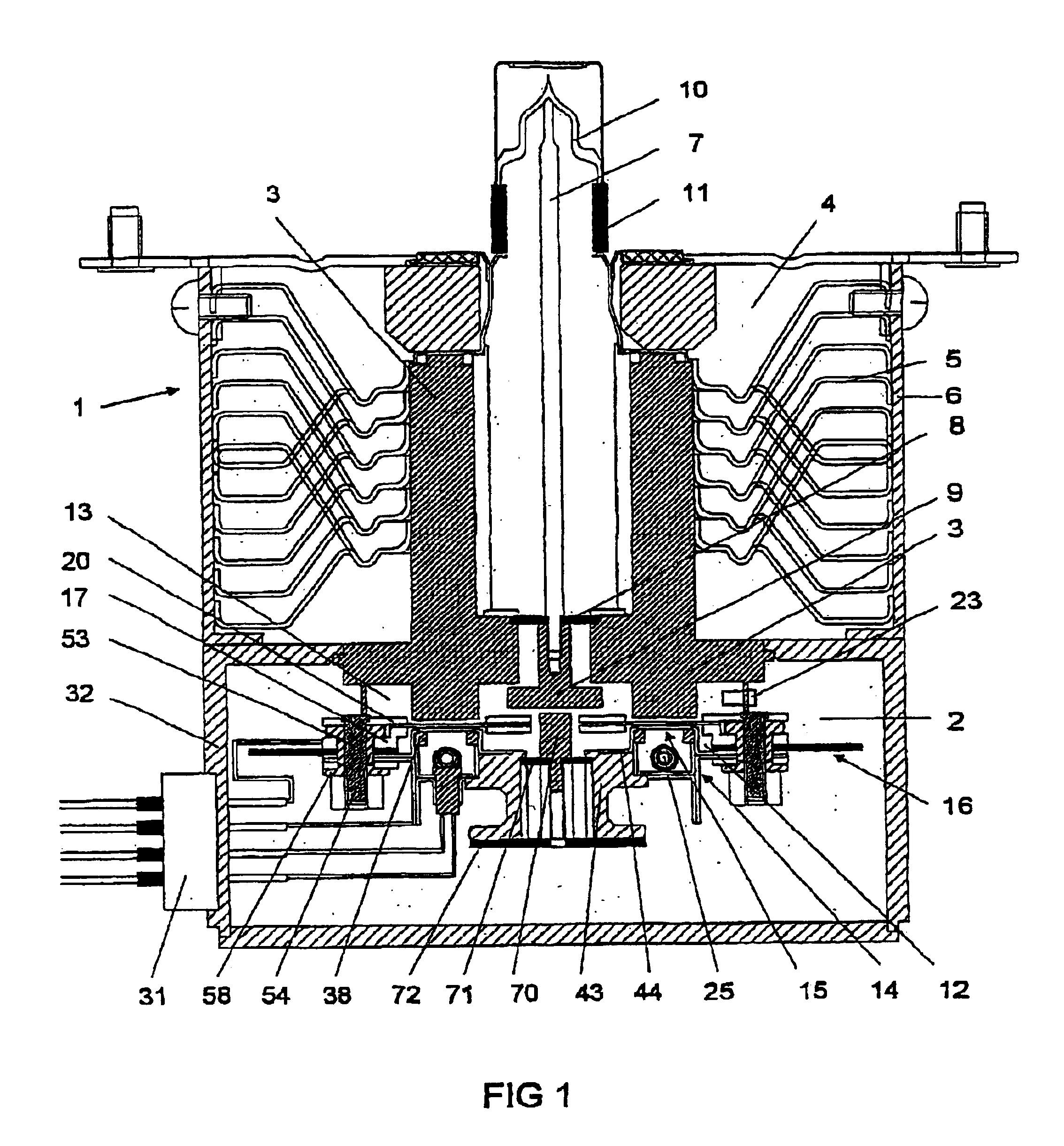
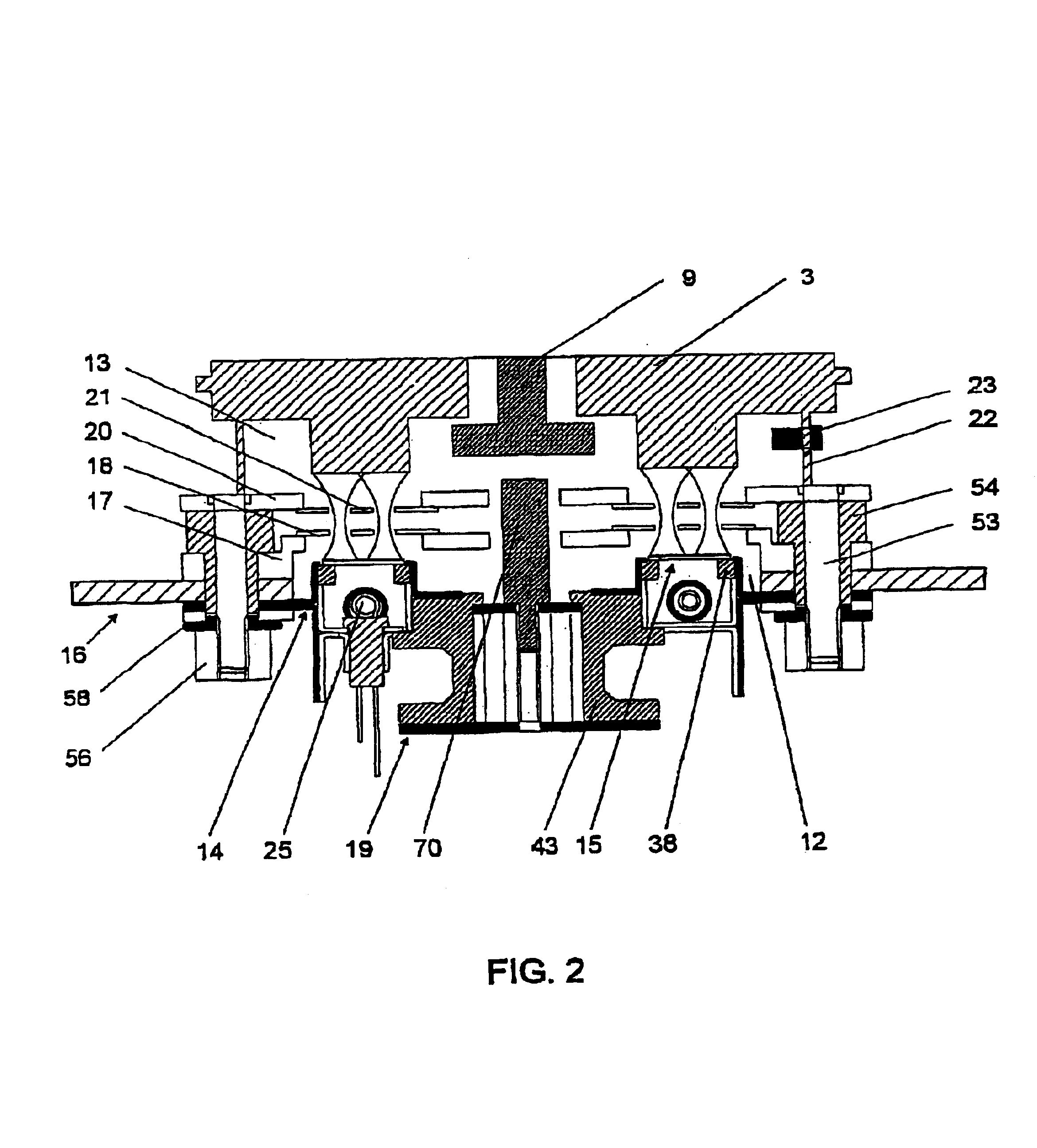
[0025]The device 1 illustrated in FIG. 1 has a vacuum chamber 2 surrounded by a housing 32, in which device a cathode arrangement, a grating arrangement and in part an anode arrangement are contained, which can be detected in more detail in FIG. 2. One part of the anode 3 fixed on the housing 32 of the vacuum chamber 2 protrudes into a cooling chamber 4, in which cooling ribs 5 are disposed between the anode 3 and the housing 6 for dissipating the heat from the anode 3. A bar-shaped antenna 7 is aligned centrally relative to the anode 3 and is insulated from the anode 3 by a ceramic disc 8. It terminates on the anode side in a coupling element 9, whilst the other end is contained in a cap 10, a ceramic cylinder 11 insulating the antenna 7 from the remaining housing.

[0026]In FIG. 2, the components which are contained in the vacuum chamber 2 are illustrated more precisely. Two resonance chambers or resonance cavities are disposed one above the other and parallel, an input cavity 12 an...


PUM


Abstract

A device is proposed for producing high-frequency microwaves, having a cathode arrangement with heatable cathodes for emitting electrons, two grating arrangements for controlling and focusing the electrons flow and an anode for recaiving the electrons passing through the grating arrangements. The cathode arrangement and the first grating arrangement and also a blocking or choke element define an output cavity forming a resonance cavity and the anode and the second grating arrangement define an output cavity likeeise forming a resonance cavity. The cathode arrangement has a monuting for the cathode such that deformation of the cathode with reduction of the spacing between the heatable cathode and grating is avoided.

Description

BACKGROUND OF THE INVENTION[0001]The invention relates to a device for producing high-frequency microwaves according to the preamble of the main claim.[0002]A device for producing high-frequency microwaves is disclosed in the U.S. Pat. Nos. 5,883,367, 5,883,369 and 5,883,386. This device has two resonance cavities, an input cavity and an output cavity, the input cavity comprising a cathode for emitting a linear electron beam, a blocking or choke structure for blocking a direct current and for transmitting a weak oscillation and a grating for focusing the electron beam and for modulating the same with respect to its density. The output cavity has a grating and an anode which receives the electron beam or the electrons thereof modulated in density, a microwave oscillation being produced. A feedback bar, by means of which the resonance cavities are coupled to each other, is connected to the input cavity and protrudes into the output cavity, as a result of which a part of the microwave ...

Claims


Application Information

Patent Timeline
Patent Type & Authority Patents(United States)
IPC IPC(8): H01J25/00H01J23/04H01J23/06H01J23/20H01J25/04
CPCH01J23/04H01J23/06H01J23/20H01J25/04
Inventor LEE, CHUN SIKLEE, HYECK-HEELEE, MIN-SUK
Owner KIST EURO KOREA INST OF SCI & TECH EURO FORSCHUNGSGMBH
Learn More