Method of unidirectional solidification of castings and associated apparatus

a technology of unidirectional solidification and castings, which is applied in the direction of manufacturing tools, transportation and packaging, other domestic articles, etc., can solve the problems of adding manufacturing steps and waste, apparatus further apparatus failing to provide for a uniform structure within the casting, etc., to achieve uniform structure, reduce the probability of cracking and/or shrinkage voids, and reduce the effect of stress

Inactive Publication Date: 2008-05-27
ARCONIC INC
View PDF2 Cites 9 Cited by
  • Summary
  • Abstract
  • Description
  • Claims
  • Application Information

AI Technical Summary

Benefits of technology

[0017]Accordingly, it is an object of the present invention to provide an improved method of directionally solidifying castings during cooling.
[0018]It is another object of the invention to provide a method of maintaining a relatively constant solidification rate during the solidification of the casting.
[0019]It is a further object of the invention to provide a casting method having minimized waste.
[0021]It is a further object of the invention to provide a casting method resulting in lower stresses and a reduced probability of cracking and / or shrinkage voids within the casting.

Problems solved by technology

This method fails to produce a uniform structure with low stresses, and would likely result in waste due to the necessity of cutting away the tin plate if it is not to form a part of the final casting.
The necessity of cutting away the portion of the casting surrounding the pipe results in added manufacturing steps and waste.
The apparatus further fails to provide for a uniform structure within the casting or the low stresses within the casting that would result from a directional solidification.
The apparatus fails to provide for a uniform structure within the casting.
It also fails to provide low stresses within the casting.
This patent fails to provide for control of the rate of solidification, for a uniform structure within the casting, or for low stresses within the casting.
The method of this patent is likely to result in waste due to the need to separate the casting from the dummy metal.
The apparatus further fails to provide for a uniform structure within the casting or the low stresses within the casting that would result from a directional solidification.

Method used


Image

  • Method of unidirectional solidification of castings and associated apparatus
  • Method of unidirectional solidification of castings and associated apparatus
  • Method of unidirectional solidification of castings and associated apparatus

Examples


Embodiment Construction

[0050]The present invention provides an apparatus and method of unidirectionally solidifying a casting, while also providing for a controlled, uniform solidification rate.

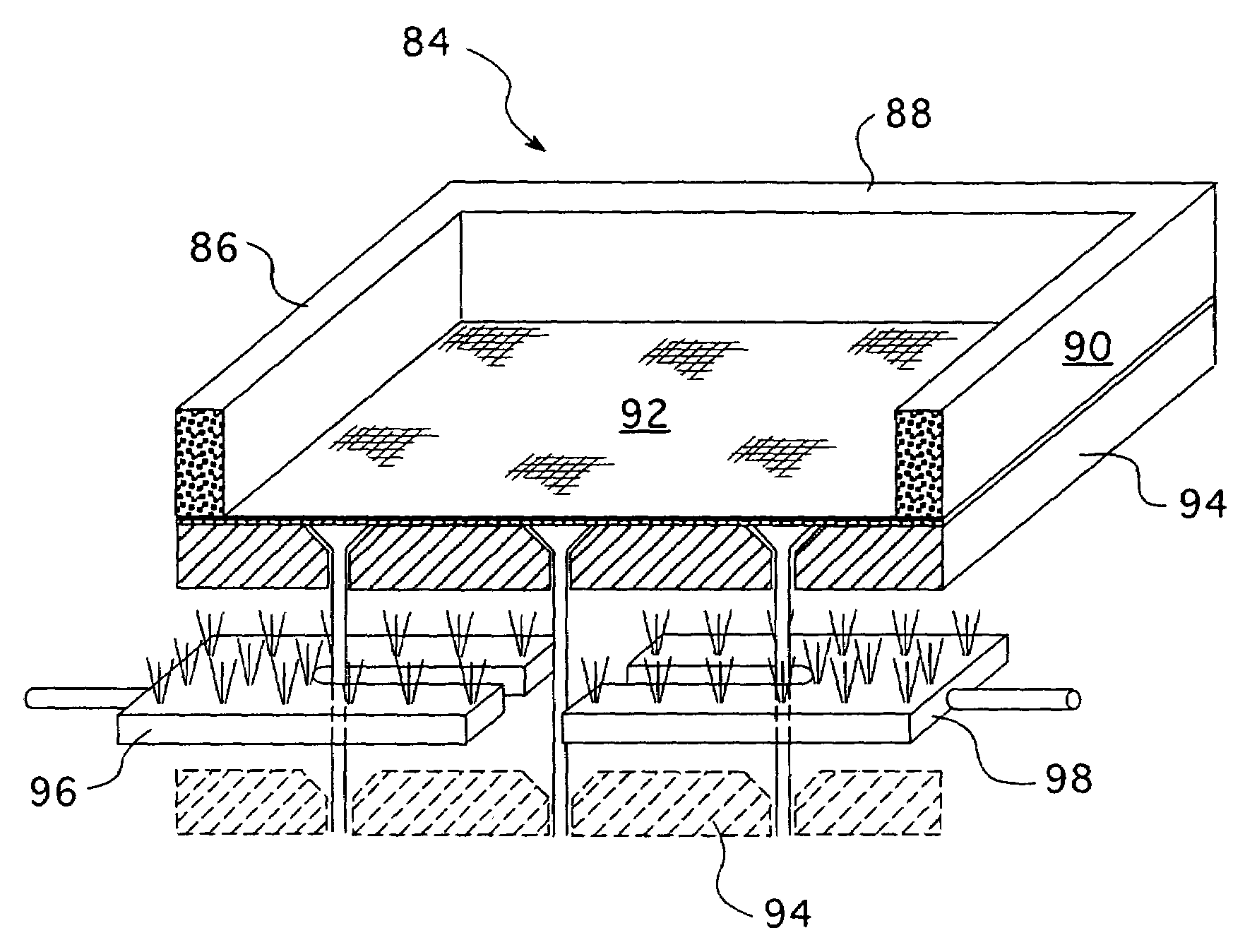
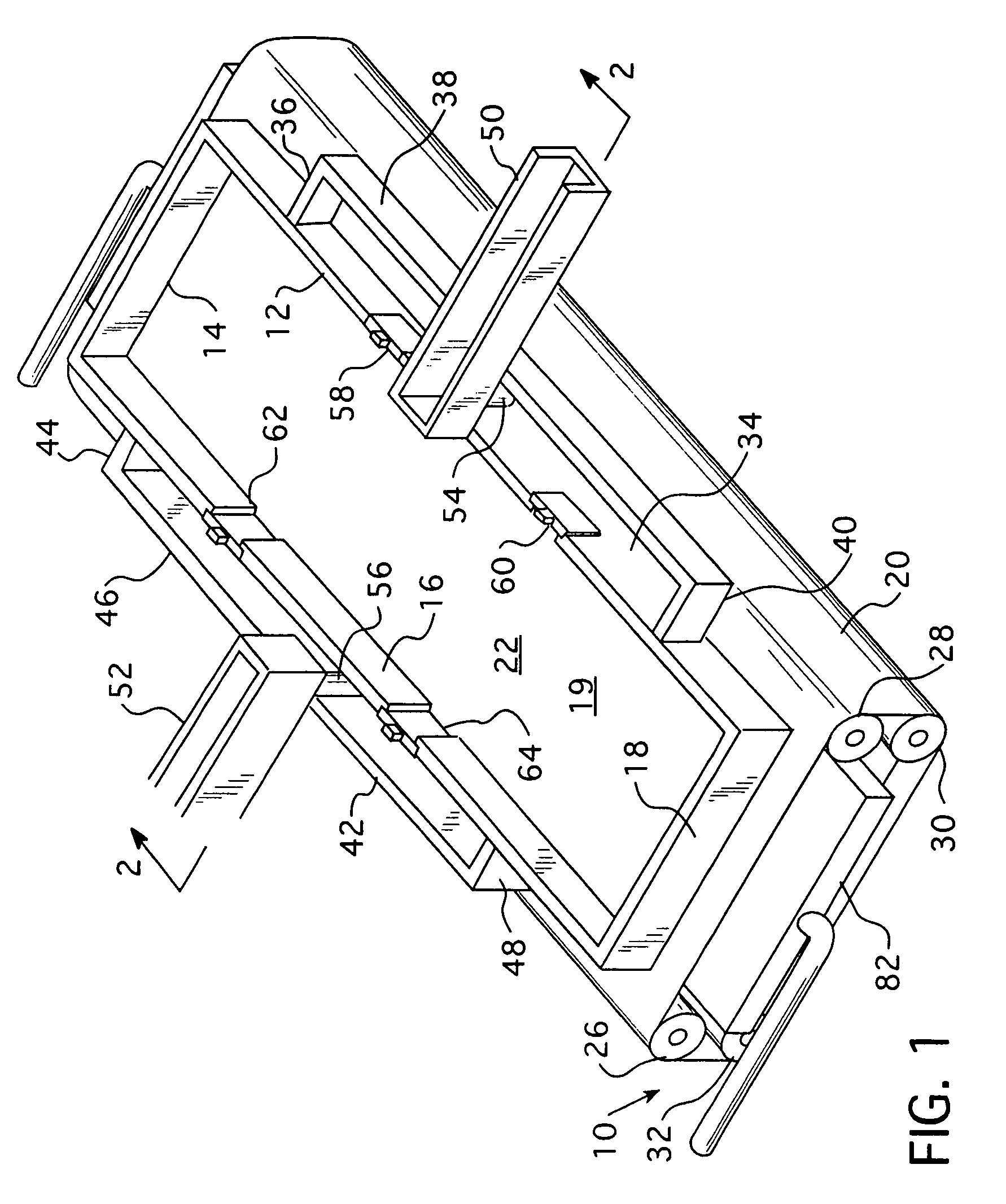
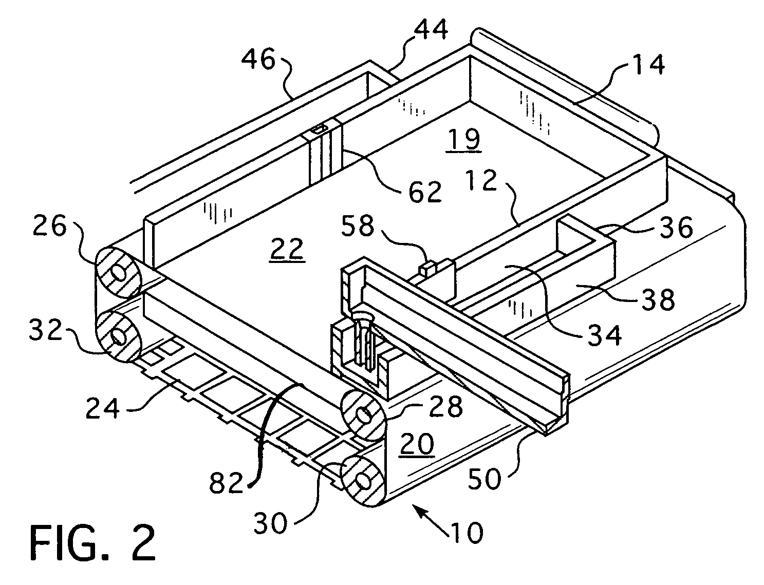
[0051]Referring to FIGS. 1-4, a mold 10 includes four sides 12, 14, 16, 18, respectively, with a mold cavity 19 defined therein. The sides 12, 14, 16, 18 are preferably insulated. A bottom 20 may be formed by a conveyor having a solid portion 22 and a mesh portion 24. The conveyor 20 is continuous, wrapping around the rollers 26, 28, 30, 32, respectively, so that either of the solid portion 22 or mesh portion 24 may selectively be placed under the sides 12, 14, 16, 18. The conveyor may be made from any rigid material having a high thermal conductivity, with examples including copper, aluminum, stainless steel, and Inconal. Note that the mesh portion 24 is a section having openings.

[0052]A molten metal feed chamber 34 defined by sides 36, 38, 40 is defined along the side 12. Likewise, a similar molten metal feed cha...


PUM

PropertyMeasurementUnit
temperatureaaaaaaaaaa
diameteraaaaaaaaaa

Abstract

Molten metal is injected uniformly into a horizontal mold from a feed chamber in a horizontal or vertical direction at a controlled rate, directly on top of the metal already within the mold. A cooling medium is applied to the bottom surface of the mold, with the type and flow rate of the cooling medium being varied to produce a controlled cooling rate throughout the casting process. The rate of introduction of molten metal and the flow rate of the cooling medium are both controlled to produce a relatively uniform solidification rate within the mold, thereby producing a uniform microstructure throughout the casting, and low stresses throughout the casting. A multiple layer ingot product is also provided comprising a base alloy layer and at least a first additional alloy layer, the two layers having different alloy compositions, where the first additional alloy layer is bonded directly to the base alloy layer by applying the first additional alloy in the molten state to the surface of the base alloy while the surface temperature of the base alloy is lower than the liquidus temperature and greater than eutectic temperature of the base alloy −50 degrees Celsuis.

Description

CROSS-REFERENCE TO RELATED APPLICATIONS[0001]This is a continuation-in-part of U.S. application Ser. No. 11 / 179,835, filed Jul. 12, 2005, the entire disclosure of which is hereby incorporated by reference.BACKGROUND OF THE INVENTION[0002]1. Field of the Invention[0003]The present invention relates to a multiple layer ingot product formed by casting. More specifically, the present invention provides an ingot cast by an apparatus and method of unidirectionally solidifying castings to provide a uniform solidification rate, thereby providing a casting having a uniform microstructure and lower internal stresses.[0004]2. Description of the Related Art[0005]Various methods of directional solidification of castings within a mold have been attempted in an effort to improve the properties of castings.[0006]An example of a presently available directional solidification method includes U.S. Pat. No. 4,210,193, issued to M. Rühle on Jul. 1, 1980, disclosing a method of producing an aluminum sili...

Claims


Application Information

Patent Timeline
Patent Type & Authority Patents(United States)
IPC IPC(8): B22D27/04B22D35/04B22D37/00
CPCB22D7/02B22D7/06B22D7/064Y10T428/12764Y10S428/939Y10T428/12493
Inventor CHU, MEN G.YU, HOGIRON, ALVAROKALLAHER, KENSHAW, JEFFREY J.
Owner ARCONIC INC
Why Eureka
Try Eureka