Head for recording and reading optical data and method of manufacturing the same

a technology for optical data and optical fiber, which is applied in the direction of heads with metal sheet cores, manufacturing tools, instruments, etc., can solve the problems of limiting the amount of information recorded with a high density due to diffraction of light, difficult to arrange information in plurality, and mechanically very fragile, so as to improve the throughput of the probe and reduce the amount of beams

Inactive Publication Date: 2008-05-27
ELECTRONICS & TELECOMM RES INST
View PDF10 Cites 5 Cited by
  • Summary
  • Abstract
  • Description
  • Claims
  • Application Information

AI Technical Summary

Benefits of technology

[0017]The present invention is contrived to solve these problems and an object of the present invention is to provide a head for recording / reproducing optical data that generates self focusing and in which an aperture is fully filled with a material having a three dimension non-linear coefficient, and method of manufacturing the same, which can reduce the amount of beam by about half wavelength, focus beam in a parabolic shape having almost no optical loss to effectively excite a near-field scanning optical microscopy to the aperture at an end portion of a probe and improve the throughput of the probe than several hundreds times than a conventional optical fiber probe.
[0022]The present invention discloses a head for recording / reading optical data having an aperture of a high transmissivity by which an optical throughput of a probe necessary to record and reproduce optical data is improved by over 100 times compared to a conventional optical fiber probe using a self-focusing phenomenon, and method of manufacturing the same.
[0023]Further, the present invention can manufacture an aperture throughput of which is improved, by effectively optically inducing its effect through a simple semiconductor process without mechanically changing a structure of a probe end portion through a multi-step semiconductor process as in a prior art, in order to improve throughput. In addition, the present invention can manufacture an aperture of a high throughput that can be arranged in plurality.

Problems solved by technology

In these cases, however, there is a limit that information is recorded with a high density due to diffraction of light, in a next generation information storage device requiring a high-density recording.
In case of the NSOM optical fiber probe, however, it is mechanically very fragile and is not easy to arrange it in plurality at a time.
Further, as throughput of light outputted to the aperture is very small (generally about 10−5˜10−7 in cases of an aperture having 100 nm in size), the NSOM optical fiber probe is very difficult to be actually used in view of recording and data processing speed.
In other words, in order to use the NSOM optical fiber probe in an optical storage device, an aperture having a high throughput is required and a probe arranged in plurality and not easily abraded mechanically is required.
Plasmon Mode, however, it is difficult to effectively excite plasmon since its exciting efficiency depends on the polarization of an incident beam.
In this case, however, as the size of the aperture representing an optimum high throughput is defined depending on the first taper region and the aperture is manufactured by a multi-step wet etch process, there is a problem that its manufacturing process is complicated.
Further, there is a problem that it could not be applied to an optical storage device of a probe mode since the end portion of the probe is very large.
In case of this structure, however, as the process of manufacturing the probe including the low-temperature oxide film formation process is complicate, there is a problem that it is difficult to make the end portion of the probe in a parabolic shape.
However, this method is almost impossible to be used.
The reason is that a mode of light reflected by the reflection film could not be effectively transferred to a mode existing in the aperture using only the first reflection film.
Also, in this case, there is a region having a large light loss same to a conventional optical fiber probe.
Therefore, there is a problem that this structure could not be applied to an optical storage device using the probe mode though it could be simultaneously applied to the probe mode and the near-field scanning optical microscopy.

Method used


Image

  • Head for recording and reading optical data and method of manufacturing the same
  • Head for recording and reading optical data and method of manufacturing the same
  • Head for recording and reading optical data and method of manufacturing the same

Examples


Embodiment Construction

[0034]The present invention will be described in detail by way of a preferred embodiment with reference to accompanying drawings, in which like reference numerals are used to identify the same or similar parts.

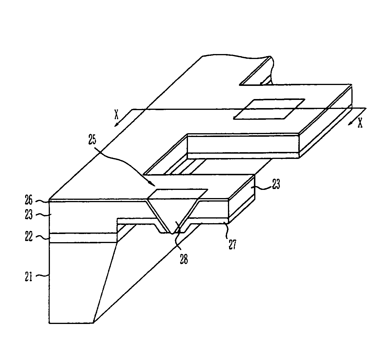
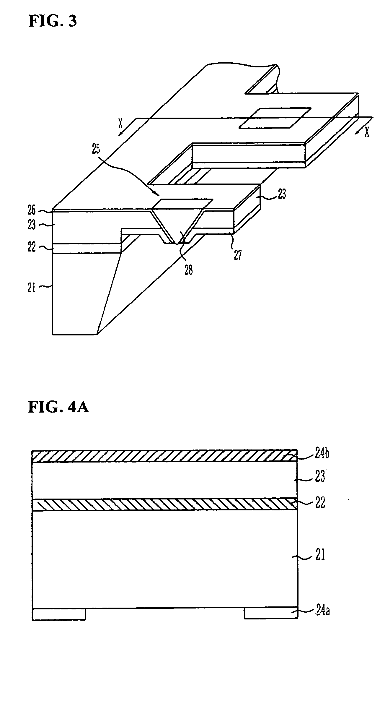
[0035]FIG. 3 is a perspective view of a head for recording / reproducing optical data according to the present invention.

[0036]Referring now to FIG. 3, the head for recording / reading optical data is mainly divided into two sections: a lower structure and an upper structure. The lower structure includes a silicon substrate 21 and finally becomes a holder of the head. The upper structure has a reverse-trapezoid shape and includes a probe having a plurality of apertures 25 filled with a non-linear material 28 and a thin metal film 27, wherein an end portion of the probe is connected to the lower structure.

[0037]The upper structure further includes a silicon deposition layer 23. A silicon oxide film 22 is formed at the boundary of the lower structure and the upper structure. A plura...


PUM

PropertyMeasurementUnit
sizeaaaaaaaaaa
optical lossaaaaaaaaaa
temperatureaaaaaaaaaa

Abstract

The present invention relates to a head for recording / reading optical data and method of manufacturing the same. The present invention completely buries an aperture with a material a third non-linear coefficient of which is great in order to induce self-focusing. Thus, the present invention can reduce the amount of beam by about one half wavelength and focus the beam in a parabolic shape having almost no optical loss. Therefore, the present invention can improve the transmissivity of the probe by several hundreds times compared to a conventional optical fiver probe, by effectively exciting a near-field scanning optical microscopy for the aperture at an end portion of the probe.

Description

[0001]The present patent application is a Divisional of U.S. patent application Ser. No. 10 / 032,989, filed Dec. 27, 2001 now U.S. Pat. No. 6,886,238.BACKGROUND OF THE INVENTION[0002]1. Field of the Invention[0003]The invention relates generally to a head for recording / reading optical data and method of manufacturing the same, and more particularly to, a head for recording / reading optical data and method of manufacturing the same capable of improving throughput of a laser beam passing through apertures in order to record / read data in a probe type mode (AFM mode) (Atomic Force Microscopy) and a NSOM (Near-Field Scanning Optical Microscopy) mode.[0004]2. Description of the Prior Art[0005]In order to store more information per unit area in an optical storage device, it is required that the wavelength of a recording optical source be reduced or the numerical aperture of a condensing lens must be increased. To satisfy such a requirement, it may be considered to develop a blue laser diode...

Claims


Application Information

Patent Timeline
Patent Type & Authority Patents(United States)
IPC IPC(8): G11B7/00G01Q60/22G11B5/127G11B11/26G11B5/147G11B7/135G11B7/22G11B11/00H01L21/311
CPCG11B7/1387G11B7/22B82Y10/00B82Y20/00Y10T29/49032Y10S29/016Y10T29/49165G11B11/26
Inventor SONG, KI BONGKIM, JEONG YONGPARK, KANG HO
Owner ELECTRONICS & TELECOMM RES INST
Why Eureka
Try Eureka