

Pulse width modulation control circuit for a multimode electrical machine, and a multimode electrical machine equipped with such a control circuit
a control circuit and multi-mode technology, applied in the direction of electrical equipment, electric energy vehicles, synchronous motors, etc., can solve the problems of insufficient current delivery in the control circuit, the overall efficiency and performance of the electrical machine designed to operate will always be inferior to the overall efficiency of the electrical machine designed to operate, and the electromechanical design of the electrical machine adapted to operate over any on-board power supply network requires compromises that modify the performan
- Summary
- Abstract
- Description
- Claims
- Application Information
AI Technical Summary
Benefits of technology
Problems solved by technology
Method used
Image

Examples
second embodiment
[0051]Diagrams (c) and (d) represent a control signal by using a reference wave in the form of a triangular wave in which, according to the ascending and descending slopes and at the maximum reference level VMLI, M it is possible to vary a conduction start time tp and a conduction end time t′p at each period p of the reference wave. When the measuring signal Mi,P becomes greater than the reference signal, the circuit 13 switches an output Ci to an active value at the time tp and when the reference signal Mip again becomes less than the reference signal Si, the circuit 13 again places its output Ci at the inactive state at the time t′p.
[0052]Such a wave form reduces the harmonic components since switchings between phases are no longer simultaneous.
third embodiment
[0053]Diagrams (e) and (f) represent a control signal by using a reference wave in the form of a trapezoidal wave in which, according to the ascending and descending slopes and at the maximum reference level VMLI, M it is possible to vary a conduction start time tp and a conduction end time t′p at each period p of the reference wave according to the same mechanism as in the aforesaid diagrams. However, the constant voltage VMLI.i part of each reference signal Si assures that a certain duration of no change in the state of bridge 4 will be assured which avoids certain anarchic switchings.
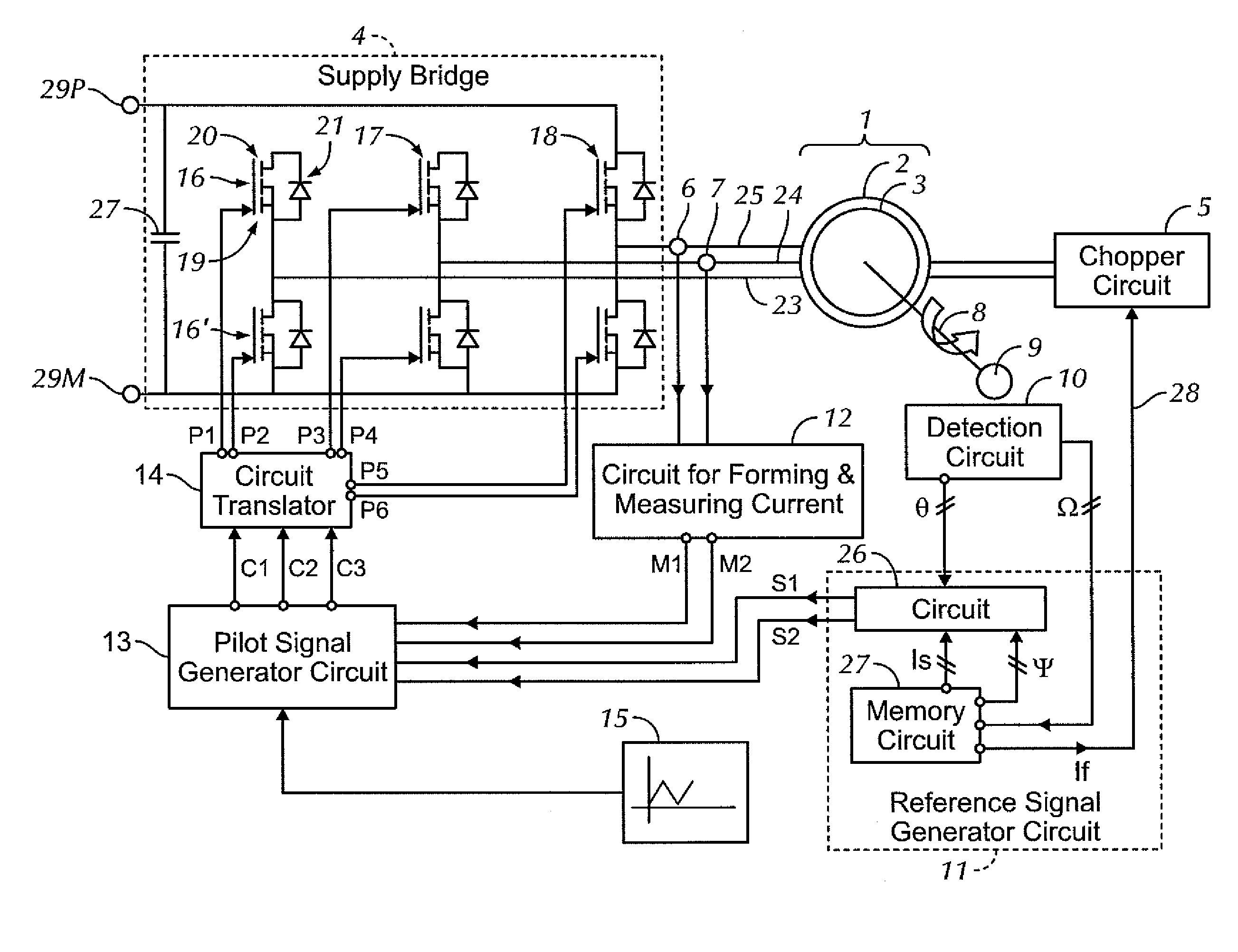
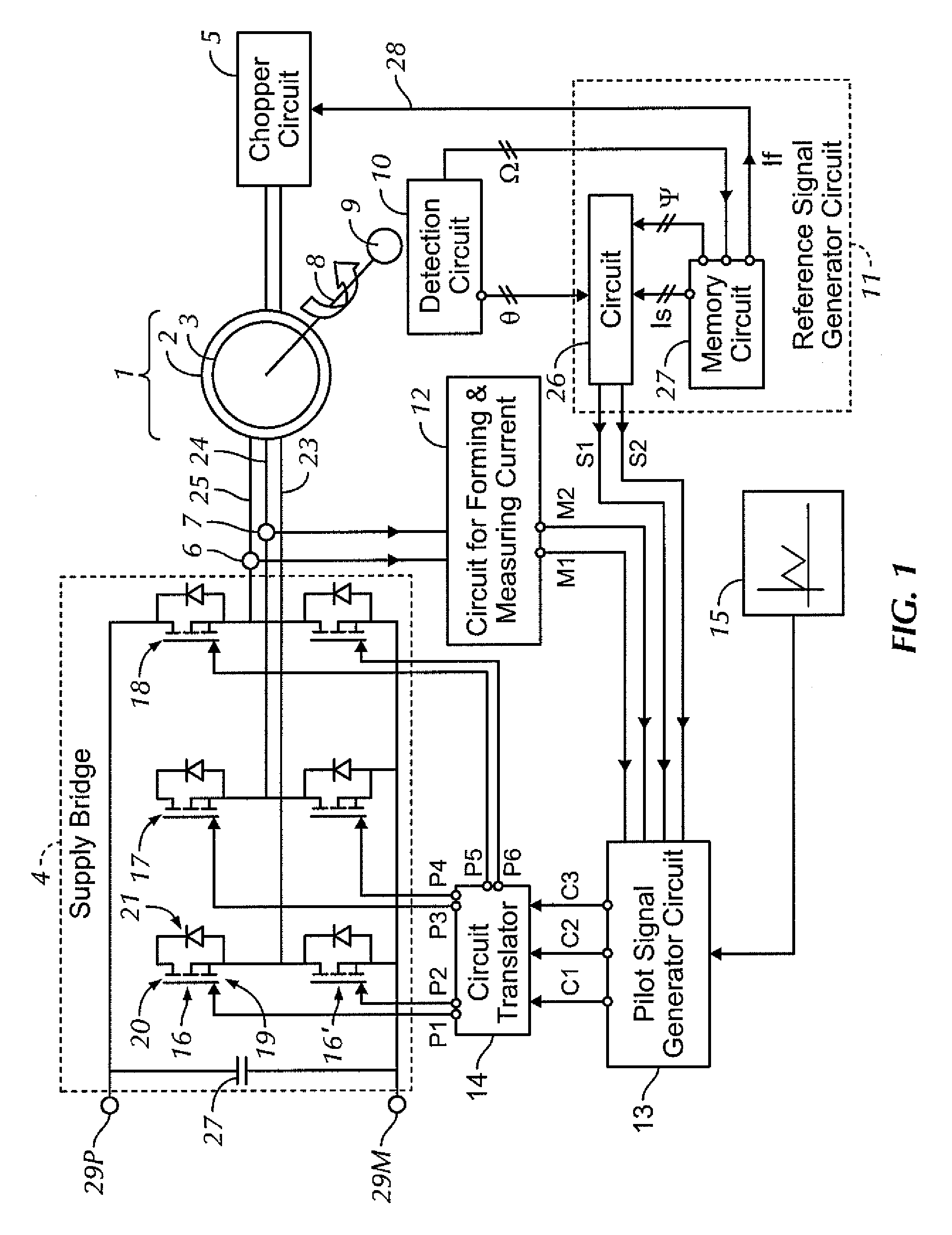
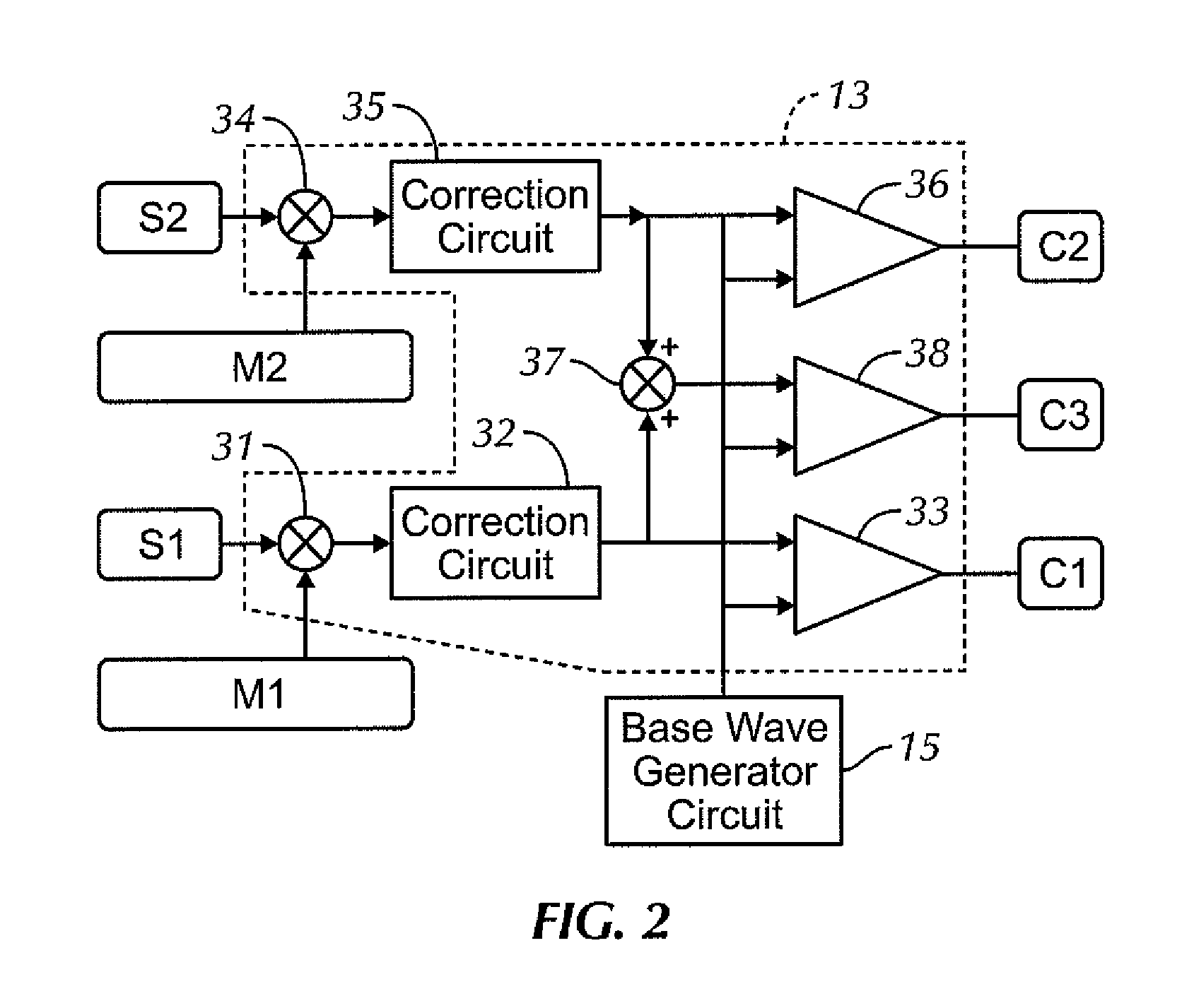
[0054]Therefore one achieves a pulse width modulation of a given frequency that may be parametered during use and with variable cyclic ratio according to the current measured in the phase as well as a reference signal that corresponds to the operation mode of the electrical machine at the time of the comparison performed in circuit 13.
[0055]For this purpose, the reference signal generator circuit 11 ...
PUM
 Abstract
Description
Claims
Application Information