Synchronous/asynchronous interface circuit and electronic device

a technology of synchronous/asynchronous interface and electronic device, which is applied in the direction of multiplex communication, generating/distributing signals, instruments, etc., can solve the problem of reducing the output of the whole synchronous circuit system

Inactive Publication Date: 2008-07-01
SEIKO EPSON CORP
View PDF5 Cites 23 Cited by
  • Summary
  • Abstract
  • Description
  • Claims
  • Application Information

AI Technical Summary

Benefits of technology

[0007]In order to address or solve the above, the synchronous / asynchronous interface circuit according to an exemplary embodiment of the present invention controls an interface between a synchronous circuit and a asynchronous circuit, and includes a finite state machine to control, in an event-driven fashion, an access cycle operated between the synchronous circuit and the asynchronous circuit, and a detection circuit to detect the beginning of the access cycle. In interfacing with the asynchronous circuit, the finite state machine controls the access cycle by transiting in states handshaking with the asynchronous circuit. Meanwhile, in interfacing with the synchronous circuit, the finite state machine controls the access cycle by transiting in states synchronizing with a global clock supplied from the synchronous circuit. Such a configuration enables embedding of the asynchronous circuit into the synchronous circuit as a part of an entire synchronous circuit system without decreasing the throughput of the whole synchronous circuit system, since the asynchronous circuit operates as a synchronous circuit at the interface with the synchronous circuit.
[0008]Preferably, the detection circuit to detect the beginning of the access cycle can include a differential circuit to differentiate a global clock supplied from a synchronous circuit and a through-latch circuit to latch a control signal that starts the access cycle when the logic state of either the rising-edge signal or the falling-edge signal of the global clock, which is output from the differential circuit, changes. Because it is asynchronous to the global clock for the asynchronous circuit to start the access cycle, the transition from a meta-stable state to a stable state can be swiftly carried out, even when the start of the access cycle is coincident with the logic state change of the global clock.
[0009]Preferably, the synchronous / asynchronous interface circuit of the present invention can further include an address latch circuit to latch the address signal output from the asynchronous circuit to the synchronous circuit and a data latch circuit to latch the data signal output from the asynchronous circuit to the synchronous circuit. The timing to output the address signal latched by the address latch circuit and to output a data signal latched by the data latch circuit into the synchronous circuit is controlled by the finite state machine in synchronization with the global clock. Such a configuration enables the timing of outputting the address signals and the date signals from the asynchronous circuit to the synchronous circuit to be synchronized with the global clock.
[0010]Preferably, the through-latch circuit included in the detection circuit that detects the beginning of the access cycle can be configured to be racing-free. By configuring the through-latch circuit in a racing-free condition, the state transitions of the finite state machine can be stabilized.

Problems solved by technology

However, trouble typically results in redesigning the asynchronous circuit block to meet the above-mentioned minimum requirement.
Moreover, even if the requirement could be met by lowering the frequency of the global clock, another problem must arise, in that the throughput of the whole synchronous circuit system decreases.

Method used


Image

  • Synchronous/asynchronous interface circuit and electronic device
  • Synchronous/asynchronous interface circuit and electronic device
  • Synchronous/asynchronous interface circuit and electronic device

Examples


Embodiment Construction

[0035]In the following, exemplary embodiments of the present invention are described with reference to the accompanying drawings.

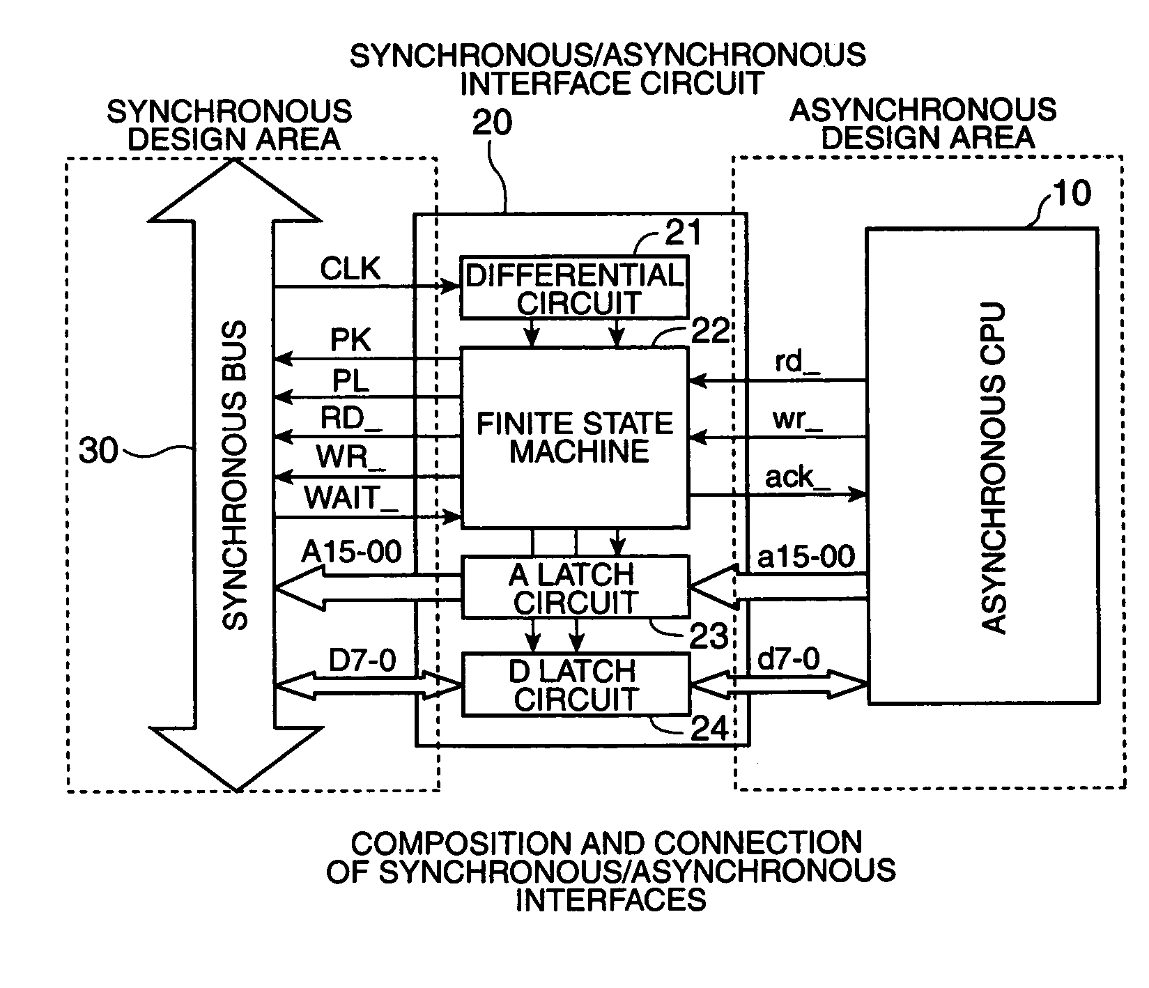
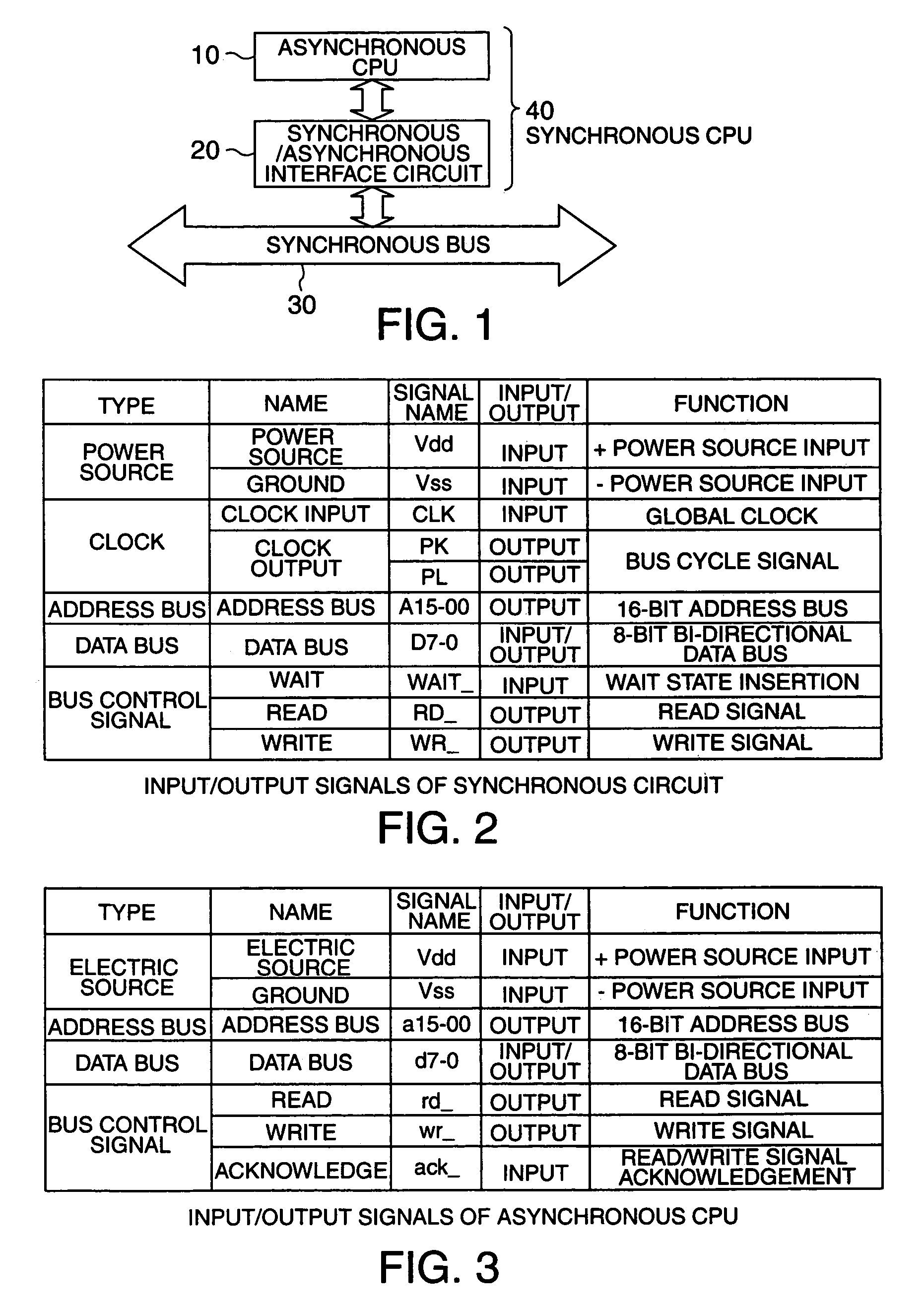
[0036]FIG. 1 illustrates an entire composition of a synchronous / asynchronous interface circuit according to an exemplary embodiment of the present invention. A synchronous / asynchronous interface circuit 20 lies between an asynchronous CPU 10 and a synchronous bus 30, linking the two. The synchronous / asynchronous interface circuit 20 is a circuit that makes the asynchronous CPU 10 apparently act as a synchronous CPU 40 for the synchronous bus 30. The synchronous / asynchronous interface circuit 20 operates in two ways. On one hand, it operates as a synchronous circuit unit driven by a global clock signal (CLK signal) at a point of connection with the synchronous bus 30. The synchronous / asynchronous interface circuit 20 satisfies the above-mentioned minimum requirement by the handshaking with the asynchronous CPU 10 regardless of the transition inner states. T...


PUM


Abstract

An exemplary embodiment provides a synchronous / asynchronous interface circuit and an electronic device for coupling an asynchronous circuit block onto a globally synchronous circuit system. A synchronous / asynchronous interface circuit according to an exemplary embodiment of the present invention includes a finite state machine that controls access cycles between a synchronous bus and an asynchronous CPU in an event-driven fashion and a detection circuit that detects beginnings of the access cycles. In interfacing with the asynchronous CPU, the finite state machine controls the access cycles by transiting in states handshaking with the asynchronous CPU. Meanwhile, in interfacing with the synchronous bus, the finite state machine controls the access cycle by transiting in states synchronizing with a global clock supplied from the synchronous bus.

Description

BACKGROUND OF THE INVENTION[0001]1. Field of Invention[0002]An exemplary embodiment of the present invention relates to techniques of coupling asynchronous circuits onto a synchronous circuit driven by a global clock. More particularly, an exemplary embodiment of the present invention relates to interface circuits to connect an asynchronous circuit to a synchronous circuit, and also relates to electronic devices including the asynchronous circuits, synchronous circuits and the interface circuits.[0003]2. Description of Related Art[0004]It is a minimum requirement for related art synchronous circuits to settle into the next state within a clock cycle. This means that, in the critical path, the sum of switching delays of sequential circuits and the setup time of a combination circuit must be sufficiently smaller than a clock cycle at the nominal voltage and temperature. The same requirement must be met when an asynchronous circuit block is embedded into a synchronous circuit system. I...

Claims


Application Information

Patent Timeline
Patent Type & Authority Patents(United States)
IPC IPC(8): G06F1/12G06F13/40H03K19/177H04L7/00
CPCG06F13/4072
Inventor KARAKI, NOBUO
Owner SEIKO EPSON CORP
Why Eureka
Try Eureka