Filter and radio communication device using the same

a radio communication device and filter technology, applied in coupling devices, electrical devices, waveguides, etc., can solve the problems of radiation loss dominant, difficult to realize a filter property having a steep skirt property, and increase in q values of resonators, so as to reduce radiation loss

Active Publication Date: 2008-07-08
KK TOSHIBA
View PDF16 Cites 6 Cited by
  • Summary
  • Abstract
  • Description
  • Claims
  • Application Information

AI Technical Summary

Benefits of technology

[0014]An object of the present invention is to provide a filter for increasing Q of a resonator by reducing a radiation loss even in a high-frequency zone; and to provide a radio communication device using the same.

Problems solved by technology

Like this, when the radiation losses of the resonators become large, it becomes hard to realize a filter property having a steep skirt property resulting from increases in Q values of the resonators.
However, the intention of providing a resonator to be used in a band with a high-frequency higher than 3 GHz causes the radiation loss dominant.

Method used


Image

  • Filter and radio communication device using the same
  • Filter and radio communication device using the same
  • Filter and radio communication device using the same

Examples


first embodiment

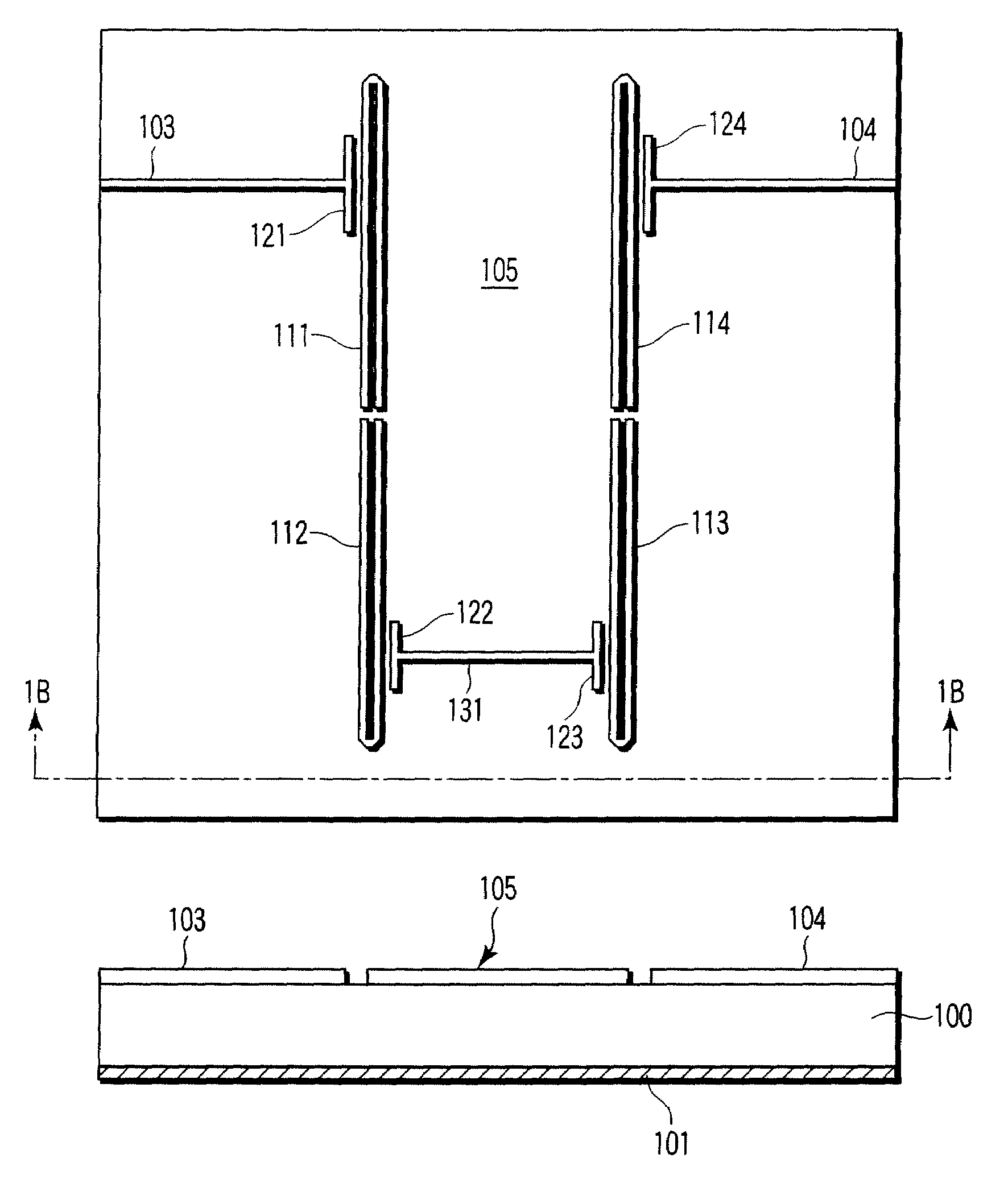
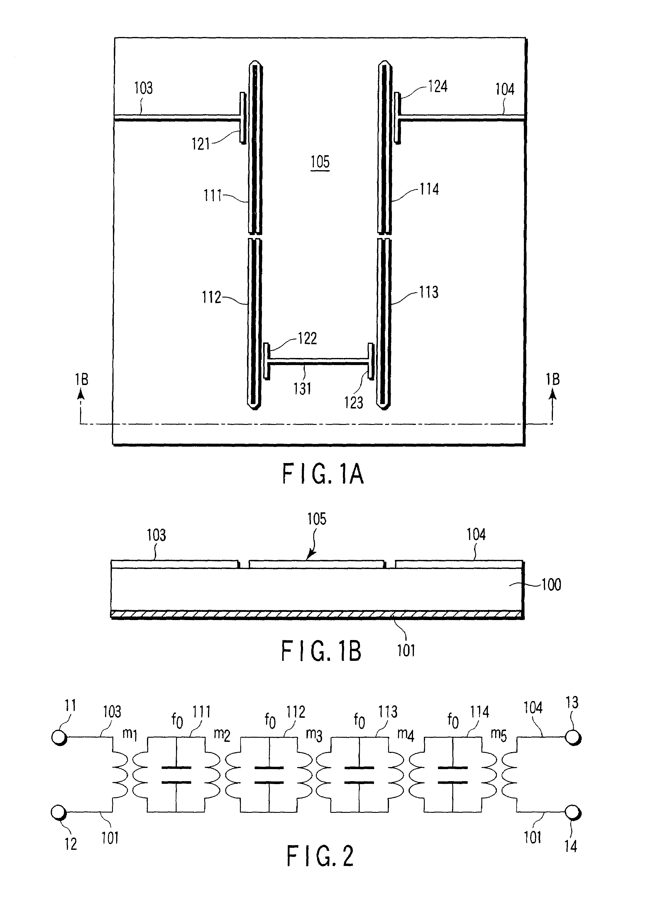
[0047]FIGS. 1A and 1B show the plane view and the cross-sectional view taken on line 1B-1B of the filter regarding the present invention, respectively. A ground plane 101 is formed on a rear surface of a dielectric substrate 100 and an input line 103, an output line (also called exciting line) 104 and a resonant unit 105 are formed on a front surface of the dielectric substrate 100. Each one end of the input line 103 and output line 104 extend up to end portions of the dielectric substrate 100 to get connected with a circuit placed outside the filter at the end portions of the dielectric substrate 100, respectively.

[0048]The dielectric substrate 100 is made of material, such as a magnesium oxide and a sapphire with thickness of around 0.1 to 1 mm. The ground plane 101, input line 103, output line 104 and resonant unit 105 are made of conductor material, for example, a metal such as copper, silver and gold, a superconductor such as niobium or niobium tin, or an oxide superconductor s...

second embodiment

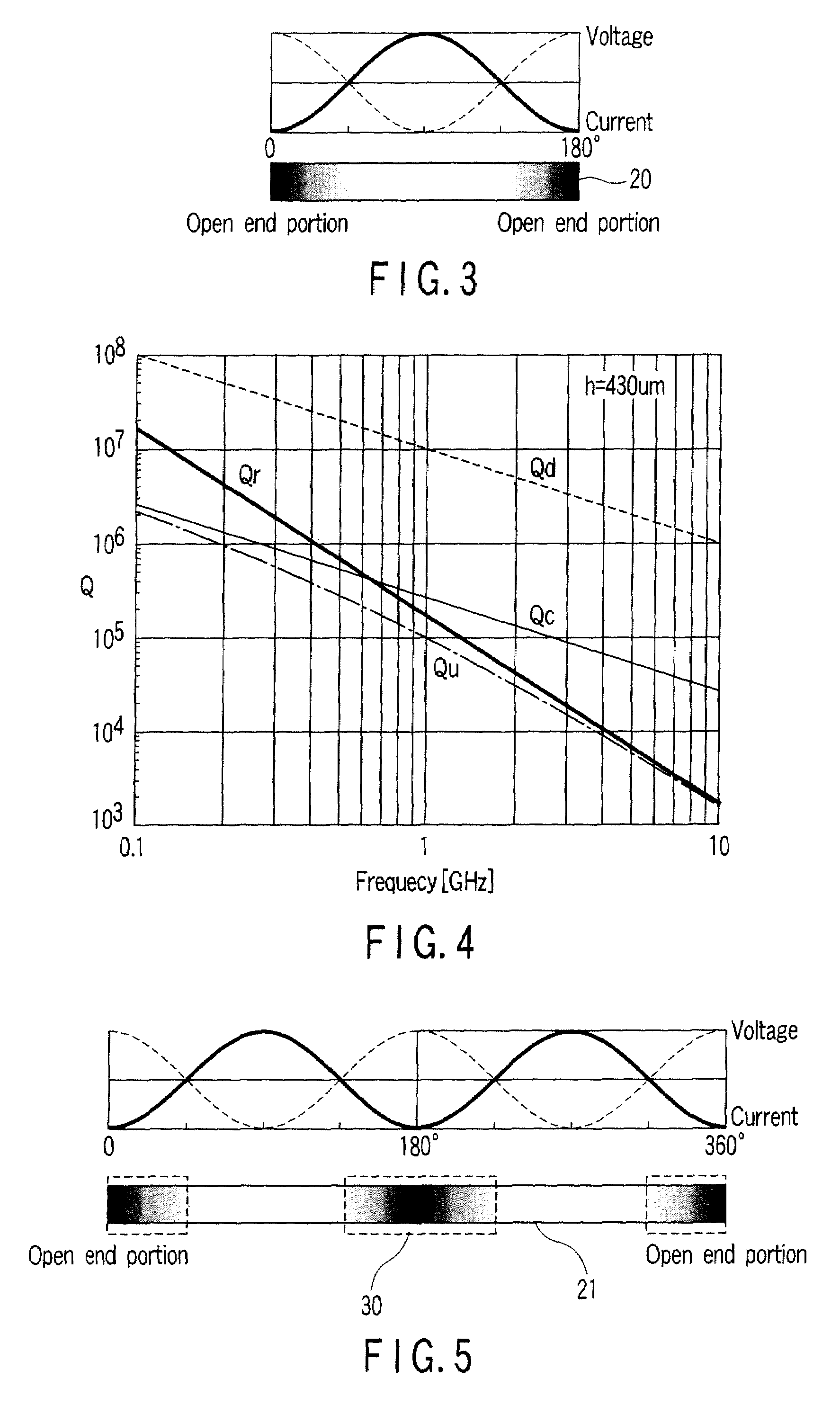
[0071]FIG. 9 shows the frequency response property obtained by the electromagnetic field analyses of the filters in FIG. 7 and FIG. 8. The horizontal and vertical axes in FIG. 9 indicate frequencies and S parameters S11 and S21, respectively. In the analyses, it is assumed that the conductor loss and dielectric loss are ‘0’ so that the analyses view only effect of a radiation property. The filter layout in the compared example shown in FIG. 8 deteriorates the Q of the resonator because radiation is generated by the coupling element 129 placed at the voltage maximum point. This deterioration of the Q increases the loss at end portions in the passband and deteriorates a property of frequency selectivity and an insertion loss property, as shown by a broken line in FIG. 9. In contrast, the filter layout in FIG. 7 based on the present invention, since the coupling elements 121-128 are placed within the ranges of ±45° from the voltage maximum points, the influence of unnecessary radiation...


PUM


Abstract

A filter includes a resonant unit which has a plurality of resonators respectively formed of each microstrip line and connected in cascade with one another, and a coupling unit which has at least one inter-resonator coupling of the resonant unit in an area within a range of ±45° (⅛-wavelength) in an electrical length from a voltage maximum point at a intermediate of the microstrip line.

Description

CROSS-REFERENCE TO RELATED APPLICATIONS[0001]This is a Continuation Application of PCT Application No. PCT / JP2006 / 316664, filed Aug. 18, 2006, which was published under PCT Article 21(2) in English.[0002]This application is based upon and claims the benefit of priority from prior Japanese Patent Application No. 2005-285325, filed Sep. 29, 2005, the entire contents of which are incorporated herein by reference.BACKGROUND OF THE INVENTION[0003]1. Field of the Invention[0004]The present invention relates to a filter and a radio communication device using the same.[0005]2. Description of the Related Art[0006]In general, a filter to limit a frequency band for a radio communication system is structured by resonant units connected in cascade. Each resonator provided in the resonant unit includes an inductor and a capacitor and adds a resister for taking account of influence of a loss. A filter of such a type can determine a frequency range of a passband and a reduction amount of a blocking...

Claims


Application Information

Patent Timeline
Patent Type & Authority Patents(United States)
IPC IPC(8): H01P1/203
CPCH01P1/20381H01P1/20372
Inventor KAYANO, HIROYUKISHIOKAWA, NORITSUGUYAMAZAKI, MUTSUKI
Owner KK TOSHIBA
Why Eureka
Try Eureka