
Differential transimpedance amplifier circuit for correlated differential amplification

a technology of differential amplification and amplifier circuit, which is applied in the direction of amplifiers with semiconductor devices only, amplifier modifications to reduce noise influence, and amplifiers with semiconductor devices/discharge tubes. it can solve the problems of environmental noise problems that are especially susceptible to detection schemes for ions, electrons and other charged particles, and suffer from some inherent limitations

Active Publication Date: 2008-07-22
NAT TECH & ENG SOLUTIONS OF SANDIA LLC +1
View PDF11 Cites 27 Cited by
  • Summary
  • Abstract
  • Description
  • Claims
  • Application Information

AI Technical Summary

Benefits of technology

The patent text describes a method to reduce noise in ion detectors caused by environmental factors such as electromagnetic interference (EMI) and thermally-induced current (thermal noise). The method involves using differential amplifiers to detect small signals while rejecting the effects of EMI and other environmental factors. The use of differential amplifiers helps to achieve high sensitivity to the analyte ions while maintaining the performance of the detector in noisy environments. The invention addresses the need for a way to reduce EMI sensitivity in ion detectors, which can be a problem in particularly noisy environments.

Problems solved by technology

When extremely sensitive detectors are employed, their extreme sensitivity makes them especially sensitive to environmental factors that can produce undesirable electronic noise that can obscure the true signal.
This leads to amplification of noise as well as of any true signal that may be present.
Detection schemes for detection of ions, electrons, and other charged particles are especially susceptible to such environmental noise problems.
The first two suffer from some inherent limitations.
The IVC type suffers from relatively poor ion sensitivity.
The electron-multiplier-based detector is susceptible to contamination in poorly evacuated mass spectrometers.
Both contamination and poor vacuum lead to progressively higher spontaneous noise and lower sensitivity.
While both IVC-based and CVC-based detectors have been used in ion-mobility-based sensors at pressures up to atmospheric pressure, both types require extensive shielding against electromagnet interference (EMI)-induced noise.
However, in a standard CTIA, the inputs are very sensitive to induced charge, so they are very susceptible to external electromagnetic wave interference (EMI) and other environmental factors.
Charge that is induced by environmental factors on the input side also contributes to the charge that builds up on the capacitor, producing an undesirable noise contribution to the measured charge.

Method used


Image

  • Differential transimpedance amplifier circuit for correlated differential amplification
  • Differential transimpedance amplifier circuit for correlated differential amplification
  • Differential transimpedance amplifier circuit for correlated differential amplification

Examples


Embodiment Construction

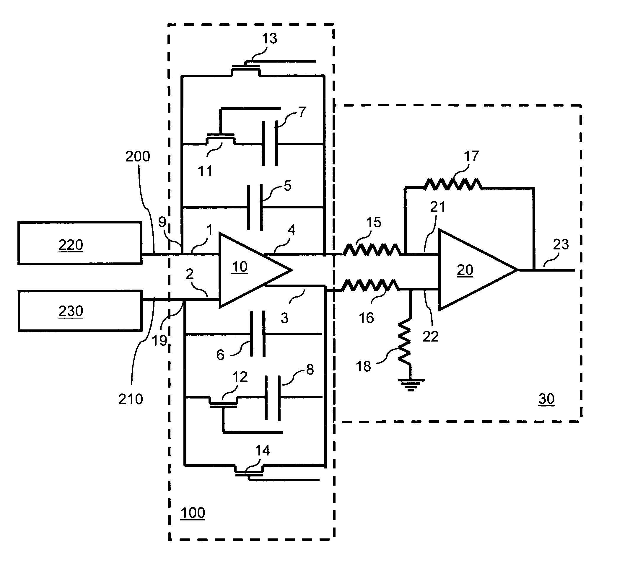
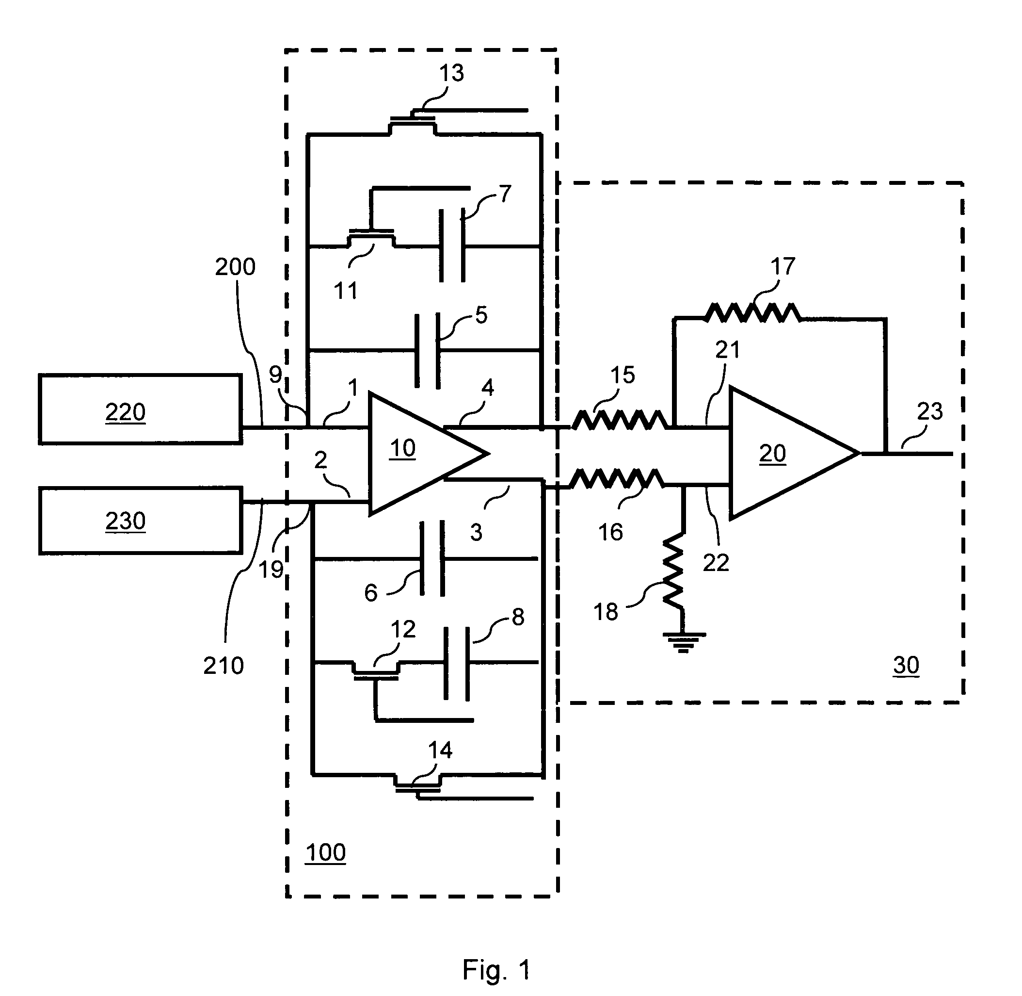
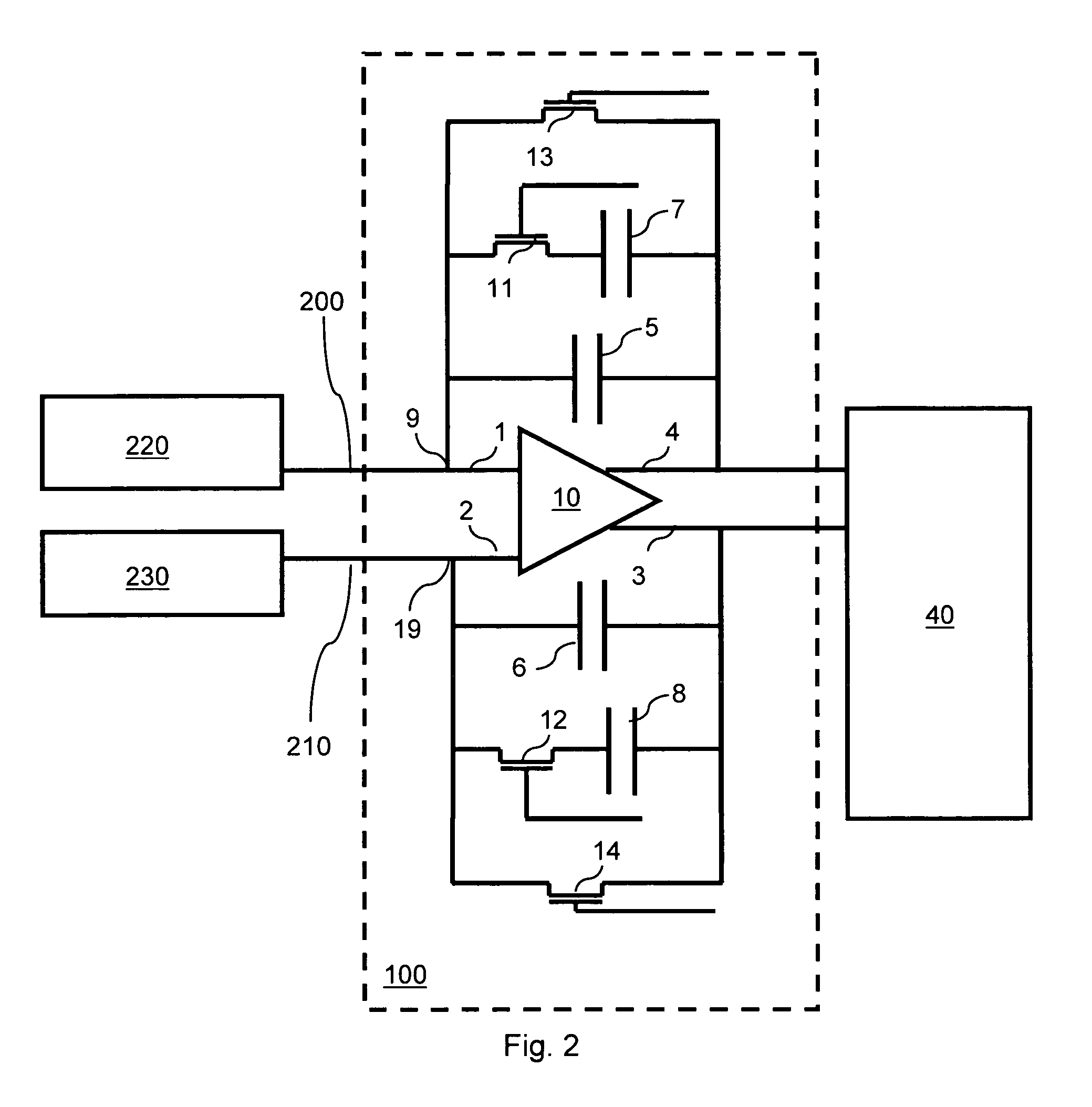
[0015]Several problems can occur when using typical differential amplification techniques. With such techniques, internal amplifier noise is uncorrelated, amplifier noise from the preamplifiers connected to the signal and reference detectors can add, and clipping can occur when noise signals are high. To overcome these and other common differential amplification problems, one can use the correlated differential amplification approach of this invention. The embodiments of the invention described herein display differential charge-to-voltage (CTV) conversion amplification with the following characteristics. Embodiments of this invention use time-correlated differential operation to minimize noise due to EMI and to provide for effective subtraction of time-correlated noise arising from external environmental sources and from the internal operation of the CVC or other parts of a detection system. True correlated noise subtraction is achieved using a differential output amplifier before ...


PUM


Abstract

A differential transimpedance amplifier circuit for correlated differential amplification. The amplifier circuit increase electronic signal-to-noise ratios in charge detection circuits designed for the detection of very small quantities of electrical charge and / or very weak electromagnetic waves. A differential, integrating capacitive transimpedance amplifier integrated circuit comprising capacitor feedback loops performs time-correlated subtraction of noise.

Description

[0001]The United States Government has rights in this invention pursuant to Department of Energy Contract No. DE-AC04-94AL85000 with Sandia Corporation.BACKGROUND OF THE INVENTION[0002]When extremely sensitive detectors are employed, their extreme sensitivity makes them especially sensitive to environmental factors that can produce undesirable electronic noise that can obscure the true signal. Some examples of such environmental factors include interfering electromagnetic waves that are periodic or random (electromagnetic interference or EMI), thermally-induced effects such as, for example, thermally induced current (dark current), circuit and instrumental operating conditions, background radiation, and other random noise sources. When such noise due to environmental factors is present, its amplification can produce a total signal that is dominated by noise contributions rather than by the true signal that one desires to measure (the signal to be measured). To achieve maximum perfor...

Claims


Application Information

Patent Timeline
Patent Type & Authority Patents(United States)
IPC IPC(8): H03F1/02H03F3/08
CPCH03F1/08H03F1/26H03F3/087H03F3/45475H03F2203/45514H03F2200/114H03F2200/264H03F2200/372
Inventor GRESHAM, CHRISTOPHER A.DENTON, M. BONNERSPERLINE, ROGER P.
Owner NAT TECH & ENG SOLUTIONS OF SANDIA LLC
Learn More