Coated article with low-E coating including IR reflecting layer(s) and corresponding method

a coating and ir technology, applied in the direction of natural mineral layered products, instruments, transportation and packaging, etc., can solve the problems of high selectivity (tsub>vis/sub>/sf) values, high visible transmission and low sf values for coated articles, and the combination of high visible transmission and low sf values is desirable, but is difficult to achieve. , to achieve the effect of good off-axis coloration, easy and cost-effective manufacturing, and less susceptible to

Active Publication Date: 2008-09-02
GUARDIAN GLASS LLC +1
View PDF20 Cites 55 Cited by
  • Summary
  • Abstract
  • Description
  • Claims
  • Application Information

AI Technical Summary

Benefits of technology

[0019]In certain example embodiments of this invention, the low-E coating of a coated article includes only two IR reflecting layers (e.g., only two silver or silver-based layers). While other numbers of IR reflecting layers may sometimes be provided, the use of two is preferable in certain instances in that more such layers are not required thereby making coatings easier and cost effective to manufacture and less susceptible to yield problems.
[0020]In certain example embodiments of this invention, a coated article is provided with first and second infrared (IR) reflecting layers of or including a material such as silver (Ag), gold, or the like. In certain example non-limiting embodiments, the bottom IR reflecting layer is designed to have a thickness greater than that of the top IR reflecting layer. For example, in certain example embodiments, the ratio (Tbottom / Ttop) of the thickness of the bottom IR reflecting layer (Tbottom) to the thickness of the top IR reflecting layer (Ttop) is at least 1.05, more preferably at least 1.10, even more preferably at least 1.15, and most preferably at least 1.17. Surprisingly, in certain example embodiments, it has been found that providing such a ratio (Tbottom / Ttop) advantageously permits good off-axis coloration to be achieved in combination with good selectivity, and without sacrificing SF, SHGC and / or LSG.

Problems solved by technology

While low SF values are typically desirable for coated articles such as IG window units, the achievement of low SF values typically comes at the expense of visible transmission and / or coloration.
It is often desirable, but very difficult, to achieve a combination of a high visible transmission and a low SF value for a coated article such as an IG window unit or the like.
Unfortunately, high selectivity (Tvis / SF) values have heretofore been difficult to achieve in certain situations.
While higher selectivities are sometimes achievable, they have come at the expense of higher SF values and / or undesirable coloration at normal and / or off-normal viewing angles such as 45 degrees.
Such high SF values may sometimes be undesirable in certain example non-limiting instances since they are indicative of coatings that in certain situations cannot block sufficient radiation from reaching a building or vehicle interior.
Too, in certain example instances, the requirement of three separate silver layers may be undesirable in certain example non-limiting situations in that such coatings are more costly and burdensome to manufacture and may be more susceptible to yield problems.
Furthermore, it is unclear from the '825 Patent whether the coatings thereof realize significant color shifts upon change in viewing angle and / or undesirable coloration.
Such color changes to red are easily picked up by observers and are sometimes considered to be objectionable.
However, such designs may sometimes suffer due to their need to position the NIR reflectance increase well outside the visible spectra from a limitation with respect to the SHGC (or SF) achievable.

Method used


Image

  • Coated article with low-E coating including IR reflecting layer(s) and corresponding method
  • Coated article with low-E coating including IR reflecting layer(s) and corresponding method
  • Coated article with low-E coating including IR reflecting layer(s) and corresponding method

Examples


example

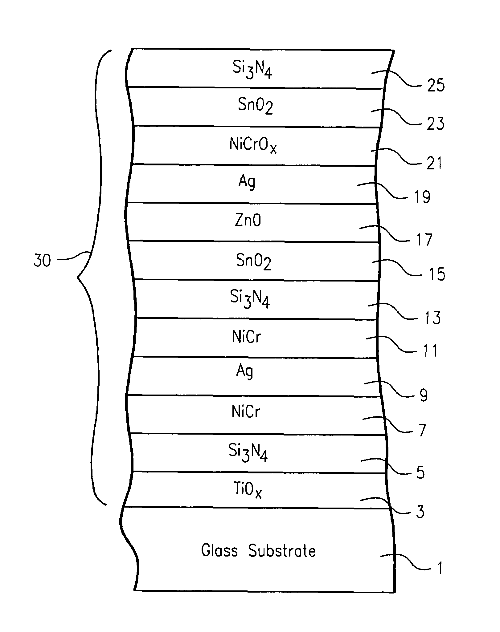
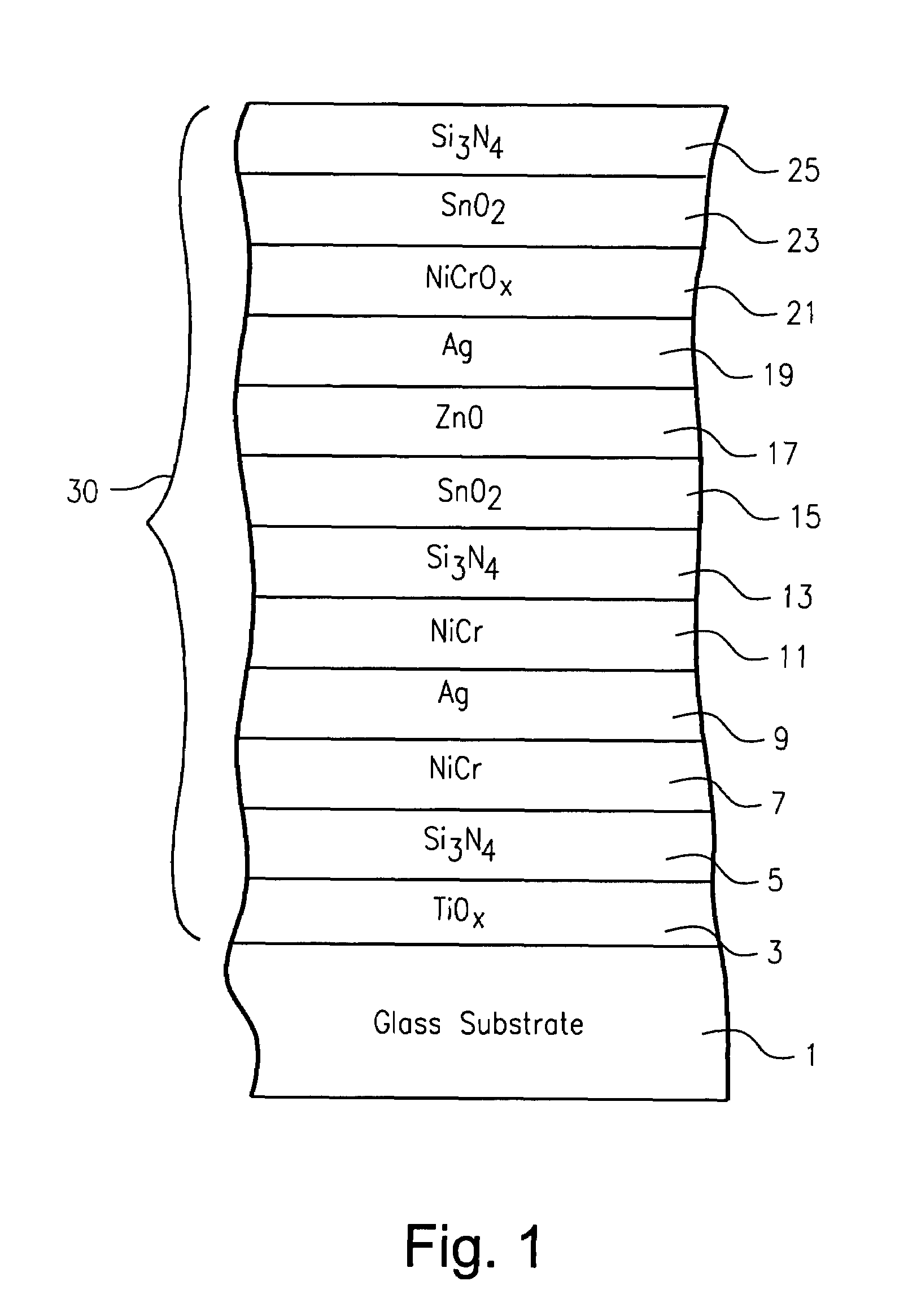
[0058]The following Example 1 was made via sputtering the coating shown in FIG. 1 on a 6 mm thick clear glass substrates 1 so as to have approximately the layer stack set forth below and shown in FIG. 1. The physical layer thicknesses are approximations, and are in units of angstroms (Å).

[0059]

Layer Stack for Example 1LayerGlass SubstrateThickness (Å)TiO260Si3N4165NiCr37.5Ag170NiCr7.5Si3N450SnO2615ZnAlOx140Ag145NiCrOx30SnO285Si3N4270

[0060]The Example coated article was not thermally tempered or heat bent in this example. All layers in this particular example were deposited via sputtering. In sputter-depositing the NiCr contact layers 7 and 11, argon (and substantially no oxygen) was used in the sputtering chamber, although some small amount of oxygen is possible in alternative embodiments. In sputtering NiCrOx contact layer 21, about 470 V and a gas flow of about 250 / 45 (Ar / O2) was used. Zinc oxide contact layer 17 was sputter-deposited using a ZnAl target using about 218 V and a ga...


PUM

PropertyMeasurementUnit
sheet resistanceaaaaaaaaaa

Abstract

A coated article is provided with a low-emissivity (low-E) layer stack for use in a window unit or the like. The layer stack, or coating, may permit the coated article to achieve one or more of a low solar factor (SF) value, a high selectivity (Tvis / SF) value, substantially neutral color at normal and / or off-axis viewing angles, and / or low emissivity. When high selectivity values are achieved, there is provided a high ratio of visible transmission to SF, which is a desirable feature in certain example instances. In certain example embodiments, asymmetric IR reflecting layer thicknesses may be used (e.g., bottom IR reflecting layer thicker than the top IR reflecting layer), and / or different contact layer for the top / bottom IR reflecting layers may be used to help achieve a combination of low SF values, high selectivity, and good coloration at normal and / or off-axis viewing angles.

Description

[0001]This application claims priority on U.S. Provisional Application No. 60 / 607,261, filed Sep. 7, 2004, and this application is also a Continuation-in-Part (CIP) of U.S. patent application Ser. No. 10 / 931,212, filed Sep. 1, 2004, and entitled “Coated Article with Low-E Coating Including IR Reflecting Layer(s) and Corresponding Method”, the disclosures of which are both hereby incorporated herein by reference.[0002]This invention relates to a coated article including a low-E coating, and / or methods of making the same. Coated articles according to certain example embodiments of this invention may be used in the context of insulating glass (IG) window units, other types of windows, or in any other suitable application.BACKGROUND OF THE INVENTION[0003]Coated articles are known in the art for use in window applications such as insulating glass (IG) window units, vehicle windows, and / or the like. In certain situations, designers of coated articles often strive for a combination of high...

Claims


Application Information

Patent Timeline
Patent Type & Authority Patents(United States)
IPC IPC(8): B32B17/06
CPCC03C17/36C03C17/3618C03C17/3626C03C17/3639C03C17/3644C03C17/366G02B5/0808G02B5/208G02B5/26C03C17/3652Y10T428/23
Inventor NEUMAN, GEORGEFERREIRA, JOSELEMMER, JEAN-MARC
Owner GUARDIAN GLASS LLC
Why Eureka
Try Eureka